Braking device for a hydraulic motor vehicle brake system

a brake system and hydraulic motor technology, applied in the direction of brake systems, vehicle sub-unit features, vehicle components, etc., can solve the problems of large construction, negative pressure brake force boosters, and ever-decreasing structural space, and achieve the effects of reducing components, structural space, weight, production and assembly effort, and cos

Active Publication Date: 2018-11-01
CONTINENTAL TEVES AG & CO OHG
View PDF2 Cites 3 Cited by
  • Summary
  • Abstract
  • Description
  • Claims
  • Application Information

AI Technical Summary

Benefits of technology

The present invention relates to a device called an elastic reaction disc used between the piston rod and the pressure piston in a vehicle's braking system. This design allows for tactile feedback during braking without requiring too much force or causing discomfort. It also eliminates the need for a high-pressure accumulator, making it lighter, more cost-effective than traditional systems.

Problems solved by technology

The technical problem addressed by this patent is finding ways to make brakes used in vehicles lighter, less expensive, easier to manufacture, provide better pedaling comfort compared to existing designs without requiring extra weight or costly equipment.

Method used


Image

  • Braking device for a hydraulic motor vehicle brake system
  • Braking device for a hydraulic motor vehicle brake system
  • Braking device for a hydraulic motor vehicle brake system

Examples


Embodiment Construction

[0026]FIGS. 1 and 2:

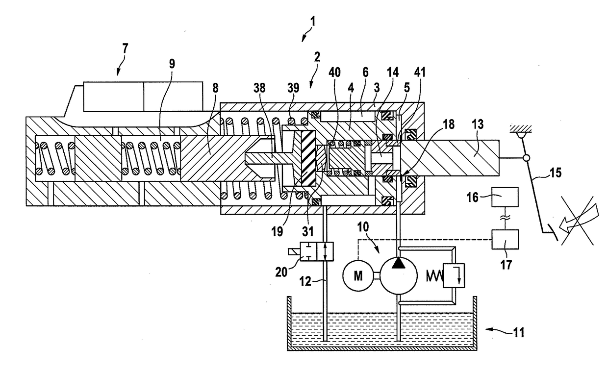
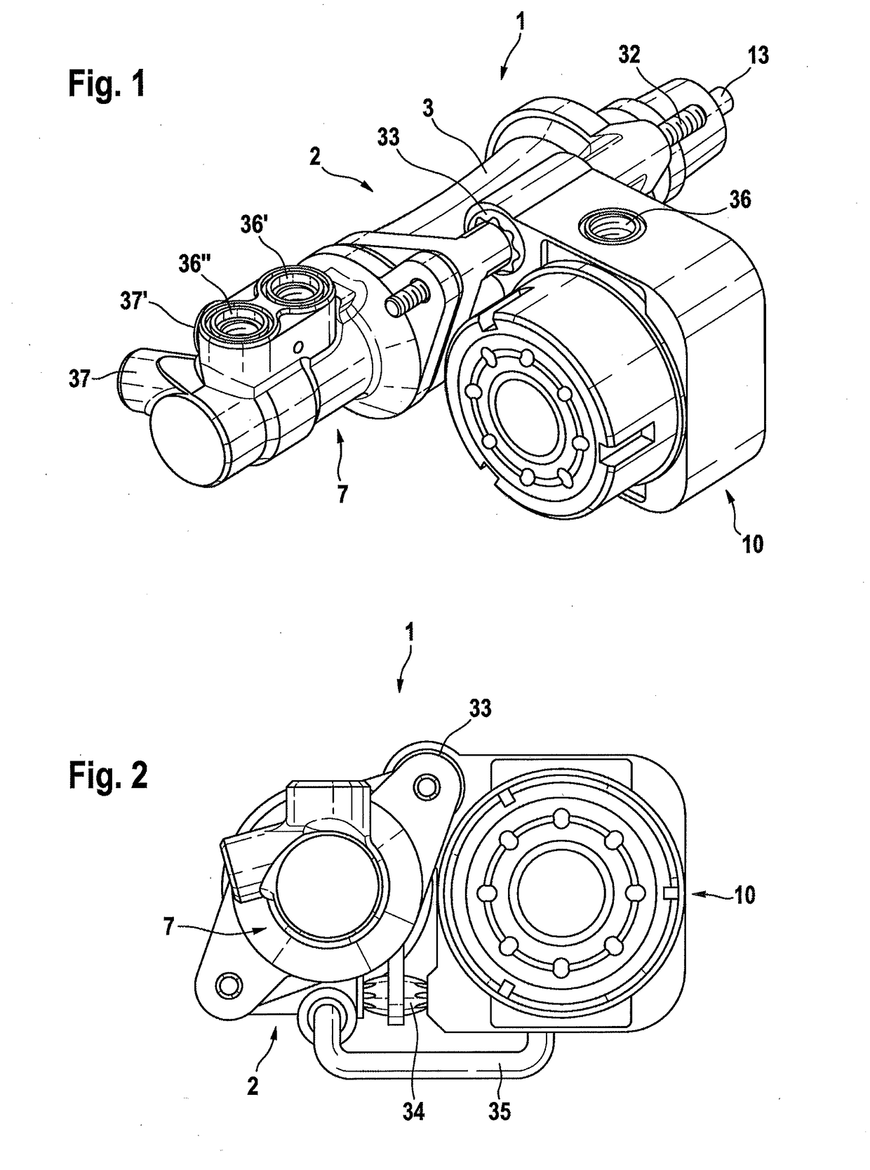
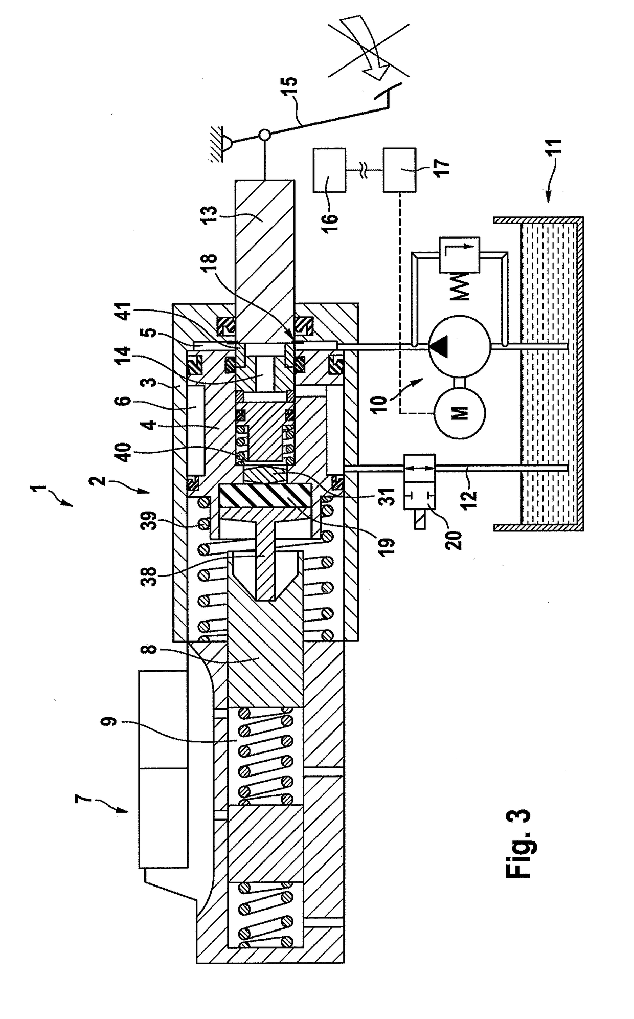
[0027]A first embodiment of the brake device 1 according to an aspect of the invention is illustrated in FIGS. 1 and 2 in external views. The brake device 1 is of modular construction and comprises substantially a hydraulic booster stage 2 with a booster housing 3, a master brake cylinder 7, and an electrically driven motor-pump unit 10.

[0028]The booster stage 2 is actuated, via an axially displaceable piston rod 13, by a brake pedal 15 (not shown here), possibly with the interposition of further conventional mechanical cornponents (not shown here).

[0029]The electric-motor-driven motor-pump unit 10 is mounted pivotably at the fastening bolt 32 in an elastic radial damper 33, and is supported and fixed against a fastening point on the booster housing 3 with the interposition of an axial damper 34. In this way, torques of the motor-pump unit 10 are, in terms of vibrations, optimally accommodated and isolated.

[0030]In the embodiment shown, the fastening bolt 32 has, on


PUM


Abstract

A modular braking device for a hydraulic motor vehicle brake system, which is optimized for remote actuation, including a hydraulic booster stage with a booster housing, a main brake cylinder mounted thereon, a booster piston which is displaceable therein and delimits a pressure chamber which is supplied directly with pressure medium by a motor pump unit.

Description


Claims


Application Information

Patent Timeline
Owner CONTINENTAL TEVES AG & CO OHG
Why Eureka
Try Eureka