Methods and devices for non-invasive root phenotyping

a non-invasive, root technology, applied in the direction of resistance/reactance/impedence, fluid resistance measurement, instruments, etc., can solve the problems of reducing crop yield or interfering with the growth cycle of plants, destroying technique, and rarely applying root traits to breeding programs

Active Publication Date: 2018-12-06
HI FIDELITY GENETICS INC
View PDF7 Cites 11 Cited by
  • Summary
  • Abstract
  • Description
  • Claims
  • Application Information

AI Technical Summary

Benefits of technology

The technical purpose described this patented technology allows plants to interact more effectively when they are growing roots inside their own tissue called the rhizome. By placing multiple small probes at different locations near the ground surface during certain stages of vegetation development, researchers can study how these interactions affects the flowering process within the Rhizo cell itself (the main part that controls photosynthesis). This knowledge will be useful tools for developing better ways to improve crop production efficiency through intervention techniques like genetic engineering.

Problems solved by technology

Technological Problem: The technical problem addressed in this patented text relates to improving methods for studying root systems architectures while avoid damaging their properties through physical modifications on specific genes. Existing tools are often difficult at detecting roots because they may affect other important aspects of crops grown indoors.

Method used


Image

  • Methods and devices for non-invasive root phenotyping
  • Methods and devices for non-invasive root phenotyping
  • Methods and devices for non-invasive root phenotyping

Examples


Embodiment Construction

[0039]The detailed description set forth below in connection with the appended drawings is intended as a description of various configurations and is not intended to represent the only configurations in which the concepts described herein may be practiced. The detailed description includes specific details for the purpose of providing a thorough understanding of various concepts. However, it will be apparent to those skilled in the art that these concepts may be practiced without these specific details. In some instances, well-known structures and components are shown in block diagram form in order to avoid obscuring such concepts.

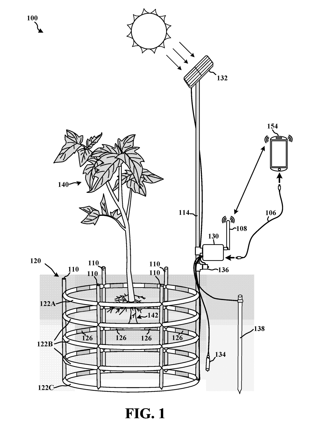
[0040]Examples of detecting roots for monitoring growth of a plant root will now be presented with reference to various electronic devices and methods. These electronic devices and methods will be described in the following detailed description and illustrated in the accompanying drawing by various blocks, components, circuits, steps, processes, algorithms, e


PUM


Abstract

The present disclosure provides for an electronic sensor for detecting a root of a plant in soil, the electronic sensor that includes a first conductor plate configured to be disposed in soil, a switch, a power supply, and signal extractor. The switch is electrically coupled to the first conductor plate and is configured to switch between a first mode and a second mode. The power supply is electrically coupled to the switch and is configured to provide an electrical charge to the first conductor plate in the first mode of the switch. The signal extractor is electrically coupled to the switch and is configured to extract a signal response at the first conductor plate in the second mode of the switch. The present disclosure further provides a second conductor plate configured to be disposed in soil adjacent to and substantially parallel to the first conductor plate. The second conductor plate is electrically coupled to ground.

Description


Claims


Application Information

Patent Timeline
Owner HI FIDELITY GENETICS INC
Why Eureka
Try Eureka