Motor diagnosis method and power conversion device using same
- Summary
- Abstract
- Description
- Claims
- Application Information
AI Technical Summary
Benefits of technology
Problems solved by technology
Method used
Image

Examples
Example
First Embodiment
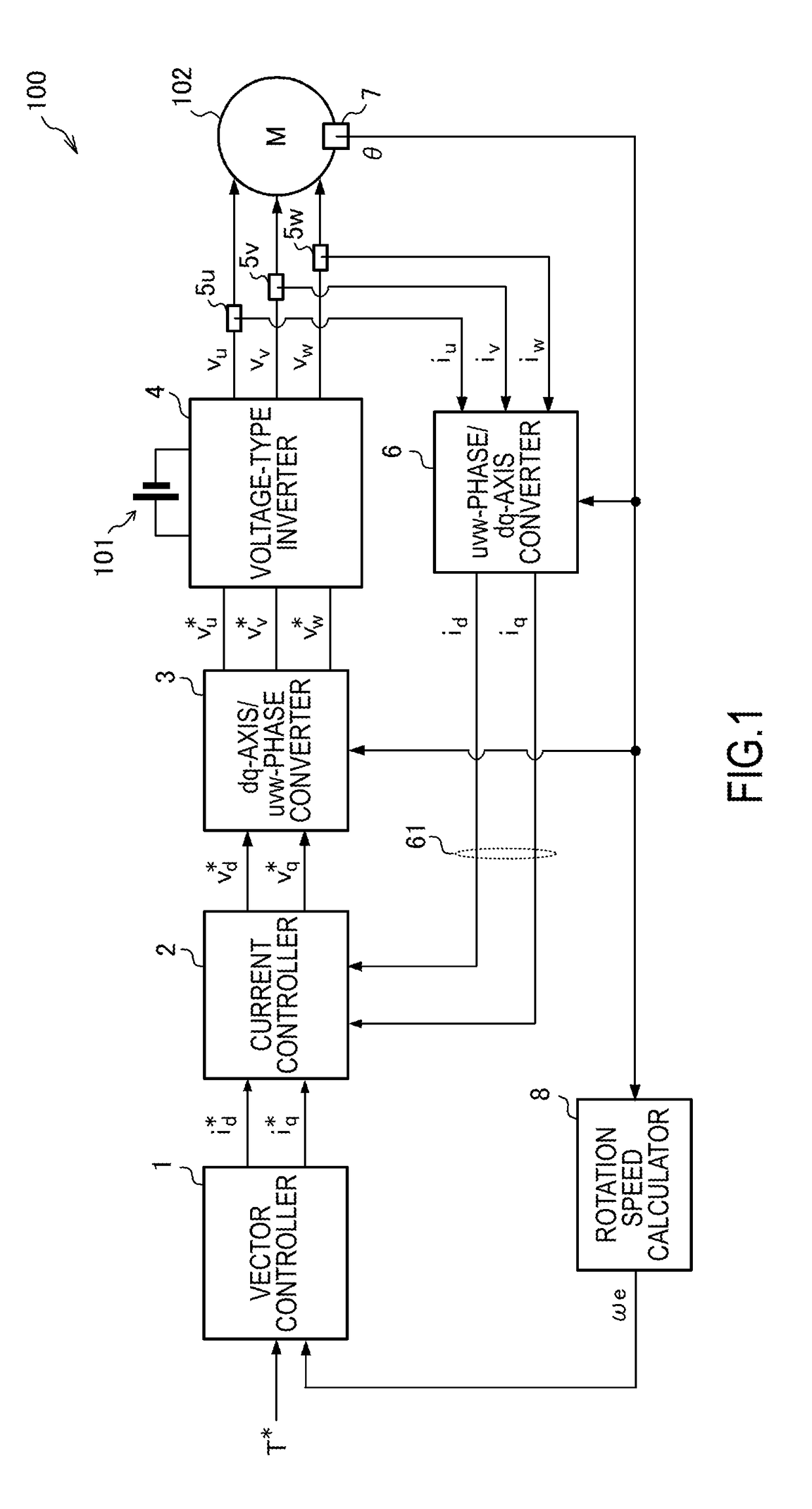
[0025]FIG. 1 is a block diagram illustrating a configurational example related to a power conversion device according to a first embodiment of the present invention.
[0026]A power conversion device 100 is a power supply device that converts power supplied from a power source and supplies the power to a motor, and is a power converter installed in, for example, a hybrid vehicle or an electric vehicle. In the present embodiment, the power conversion device 100 converts direct current (DC) power to be supplied from a power source 101 to a motor 102 to alternating current (AC) power.
[0027]The power source 101 supplies power to the motor 102. The power source 101 is realized by, for example, a battery or a fuel cell. As a battery which can be used as the power source 101, mention may be made of a lithium ion battery and the like.
[0028]The motor 102 is an AC motor that is driven by AC power. The motor 102 is realized by, for example, a synchronous motor such as a permanent mag
Example
Second Embodiment
[0142]FIG. 10 is a flowchart illustrating a processing procedure example related to a diagnosis method of the motor 102 according to a second embodiment of the present invention.
[0143]In the diagnosis method of this embodiment, the process of step S910 of the diagnosis method shown in FIG. 8 is replaced with the process of step S920. The processing content besides step S920 is the same as the processing content shown in FIG. 8, and thus the steps will be assigned the same reference numerals and explanations thereof will be omitted.
[0144]In step S920, if the absolute value of the deviation of the phase angle β is smaller than the first defined value Dth1, the motor diagnosis processing unit 200 determines that there are no insulation abnormalities, and subsequently executes a rotating diagnosis process for diagnosing the internal state of the motor 102 when the motor 102 is in a rotating state.
[0145]FIG. 11 is a flowchart illustrating an example of the rotating diagnosi
Example
Third Embodiment
[0163]FIG. 12 is a block diagram illustrating a configurational example of the motor diagnosis processing unit 200 according to a third embodiment of the present invention.
[0164]The current controller 2 is provided with an induction voltage constant multiplier 25 in addition to the constitution of the current controller shown in FIG. 6, and the motor diagnosis processing unit 200 includes the non-rotating voltage waveform setting unit 201, a torque observer 220, and a magnet abnormality determination unit 230.
[0165]The induction voltage constant multiplier 25 multiplies the d-axis voltage command value vd* output from the d-axis controller 22 by an estimated value Kê of the induction voltage constant. The estimated value Kê of the induction voltage constant is calculated using, for example, a predetermined calculation equation or map, etc., and is set in the induction voltage constant multiplier 25. The induction voltage constant multiplier 25 outputs the d-axis volta
PUM
 Abstract
Description
Claims
Application Information
 - R&D Engineer
- R&D Manager
- IP Professional
- Industry Leading Data Capabilities
- Powerful AI technology
- Patent DNA Extraction
Browse by: Latest US Patents, China's latest patents, Technical Efficacy Thesaurus, Application Domain, Technology Topic.
© 2024 PatSnap. All rights reserved.Legal|Privacy policy|Modern Slavery Act Transparency Statement|Sitemap