Large-load and high-frequency in-situ tension and fatigue tester based on X-ray imaging

A fatigue testing machine and in-situ stretching technology, applied in the direction of applying stable tension/compression to test the strength of materials, using radiation for material analysis, and using applied repetitive force/pulsation force to test the strength of materials, etc., can solve the problem that cannot be exerted Advanced light source detection capabilities, inability to test and characterize high-strength materials, long loading time and other issues, to achieve long life, high load, and fast frequency response

Pending Publication Date: 2019-06-14
SOUTHWEST JIAOTONG UNIV
View PDF1 Cites 4 Cited by
  • Summary
  • Abstract
  • Description
  • Claims
  • Application Information

AI Technical Summary

Problems solved by technology

However, worldwide research on in-situ imaging loading mechanisms based on high-energy X-ray imaging still cannot meet people's urgent needs for new high-performance materials and service behavior evaluation, for example, combining synchrotron radiation X-rays to penetrate materials with different densities Capacity, for high-strength aluminum alloys, the peak force of low-cycle fatigue loading of 2mm diameter samples is above 1500N; for add

Method used


Image

  • Large-load and high-frequency in-situ tension and fatigue tester based on X-ray imaging
  • Large-load and high-frequency in-situ tension and fatigue tester based on X-ray imaging
  • Large-load and high-frequency in-situ tension and fatigue tester based on X-ray imaging

Examples


Example Embodiment

[0034] The present invention will be described in detail below in conjunction with the drawings.

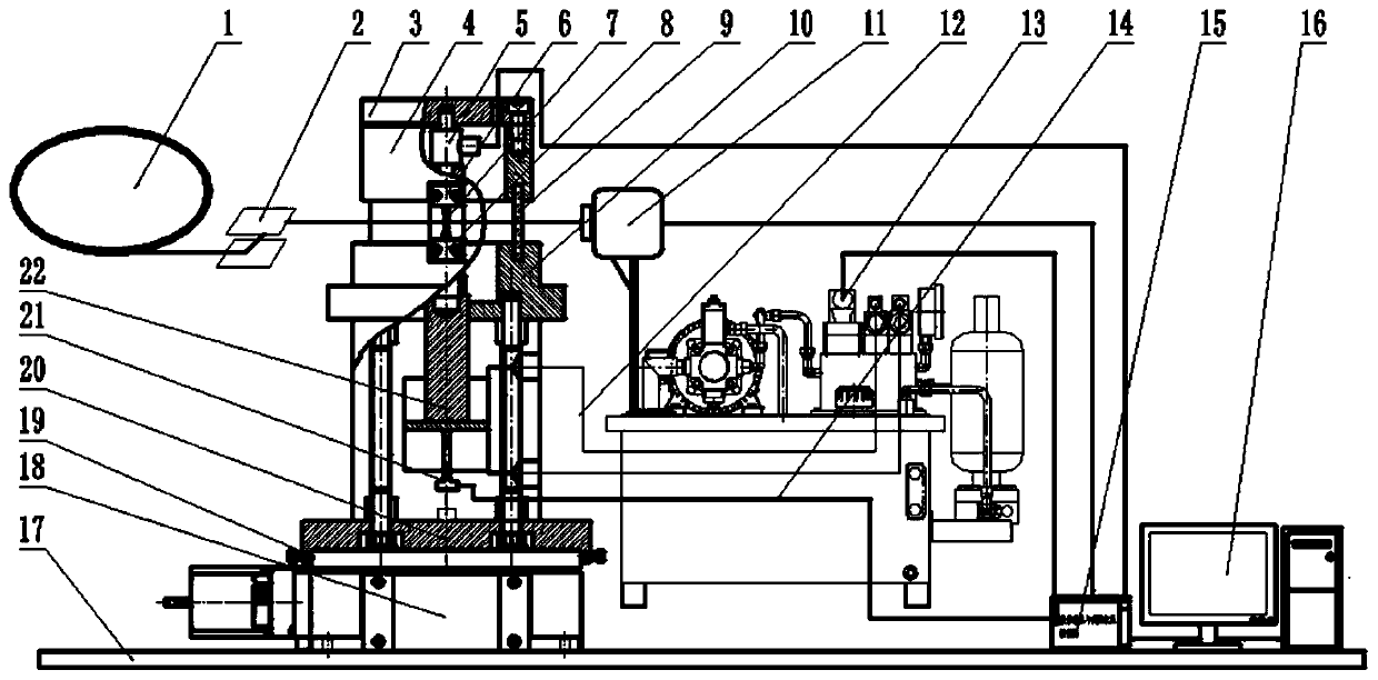
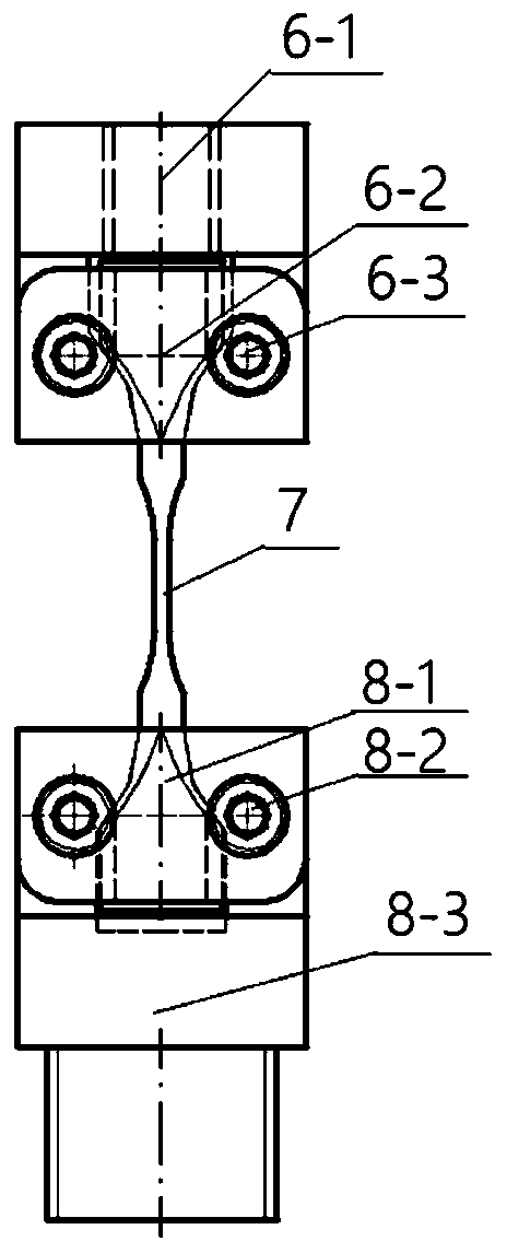
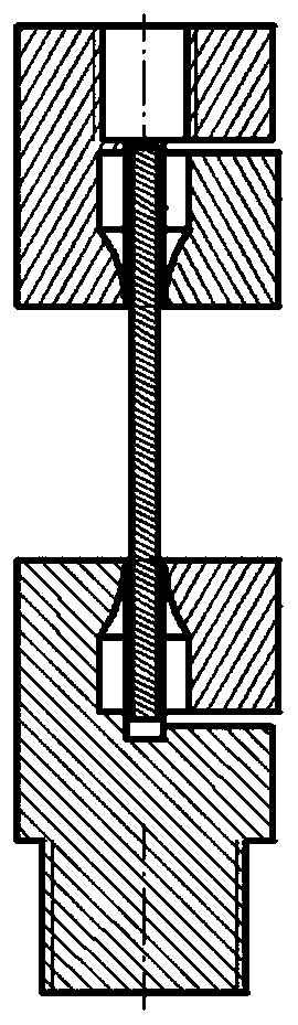
[0035] In the figure, 1 is a synchrotron radiation source, 2 is a monochromator, 3 is a top cover, 4 is a support tube, 5 is a load cell, 6 is an upper clamp, 7 is a sample, 8 is a lower clamp, and 9 is a transparent enclosure , 10 is the light source experiment platform, 11 is the X-ray detector, 12 is the hydraulic oil pipe, 13 is the electro-hydraulic servo valve, 14 hydraulic station, 15 data acquisition and controller (ie data acquisition and control unit), 16 data processing unit, 17 is the light source experiment platform, 18 is the imaging platform, 19 is the locking screw, 20 is the base of the testing machine, 21 is the displacement sensor, and 22 is the servo hydraulic cylinder.

[0036] figure 1 Shown, a large-load high-frequency in-situ tensile and fatigue testing machine based on X-ray imaging, including a data processing unit 16, a hydraulic station 14, and a light source


PUM


Abstract

The invention discloses a large-load and high-frequency in-situ tension and fatigue tester based on X-ray imaging. An imaging displacement stage can be rotatably mounted on a test platform; a base isfixed on the imaging displacement stage, a rack is arranged on the base, a servo hydraulic cylinder is arranged on the rack, a lower clamp is rotatably connected to an upper end of a piston rod of thehydraulic cylinder, a support seat platform is fixed on four uprights of the rack; a support tube is located at an upper side of the support seat platform, a transparent cover is embedded between thesupport seat platform and the support tube; an upper clamp is fixed on the support tube; an electrolyte servo valve is connected with an upper oil chamber and a lower oil chamber of the hydraulic cylinder; a load sensor, the electrolyte servo valve and a X-ray detector are orderly connected with a data collection and control unit and a data processing unit. The tester disclosed by the invention has the features of being large in load, high in frequency, small in volume, and high in precision.

Description


Claims


Application Information

Patent Timeline
Owner SOUTHWEST JIAOTONG UNIV
Why Eureka
Try Eureka