Aircraft rotational joint with a slip-ring device for electrical energy transmission

a technology of electrical energy transmission and slip-ring, which is applied in the direction of power amplification, transportation and packaging, airflow influencers, etc., can solve the problem that the unused section cannot serve independently for electrical energy transmission, and achieve the effect of reducing the overall size of the rotational joint, reducing electrical resistance, and improving electrical contact between the contact element and the ring segmen

Inactive Publication Date: 2019-01-17
AIRBUS OPERATIONS LTD
View PDF0 Cites 0 Cited by
  • Summary
  • Abstract
  • Description
  • Claims
  • Application Information

AI Technical Summary

Benefits of technology

In this patent, there describes different ways to improve the performance of a slip-ring device used in rotating joints such as those described by the patents. These improvements include reducing the size and number of components needed, improving the efficiency of power transfer, increasing resistance against vibration, simplifying assembly, and enhancing resistance against vibrations. Additionally, it includes mechanisms that allow for better control over the electrical connection between the contact elements and rings.

Problems solved by technology

This patent describes different types of slip ring devices used in rotating joints that transfer electricity from one component to another. These devices include two main components - a metal ring attached to the rotor's stationary part and a contact element for this metal ring.

Method used


Image

  • Aircraft rotational joint with a slip-ring device for electrical energy transmission
  • Aircraft rotational joint with a slip-ring device for electrical energy transmission
  • Aircraft rotational joint with a slip-ring device for electrical energy transmission

Examples


Embodiment Construction

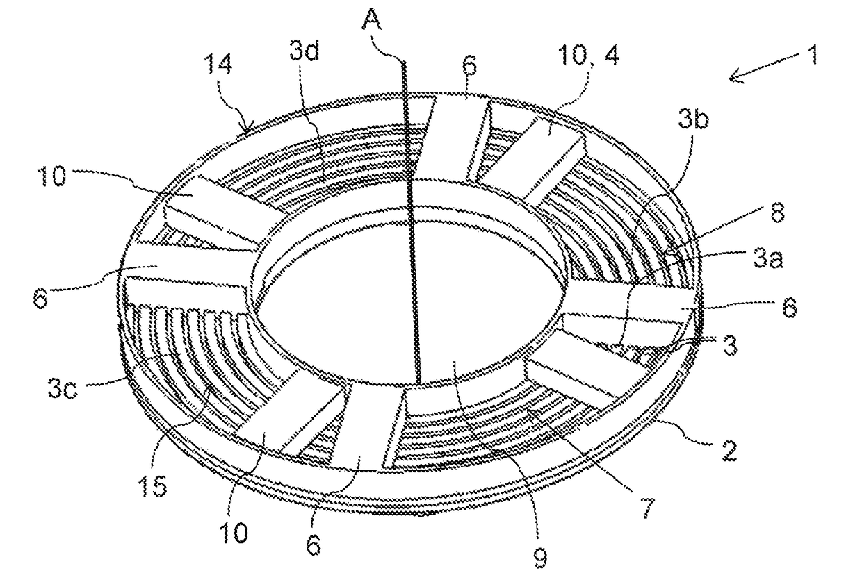
[0038]FIG. 1 schematically shows the inside of a slip-ring device 1 of an aircraft rotational joint. The rotational joint is used for movably or rotatably connecting a foldable wing tip device to a main wing of an aircraft. The slip-ring device 1 is arranged for electrical energy transmission through an aircraft rotational joint. It comprises a first member 2 attached on a first part of the rotational joint. The first member has a plurality of arcuate conductive ring segments 3. In the embodiments shown in the Figures the ring segments are metal ring segments 3. Only two of the ring segments 3 have been indicated with reference numbers to keep the drawings intelligible. The ring segments 3 are electrically isolated from each other, e.g., by arranging them spaced apart from one another. Further, the slip-ring device comprises a second member (not shown in FIG. 1) which is rotatable relative to the first member about a common rotational axis A which is also the axis of rotation of the ai


PUM


Abstract

An aircraft rotational joint comprises a slip-ring device arranged for electrical energy transmission through the rotational joint. The slip-ring device comprises a first member attached to a first part of the rotational joint. The first member has a plurality of arcuate metallic ring segments and all these ring segments are isolated from each other and are spaced apart from each other. Further, the slip-ring device comprises a second member which is rotatable relative to the first member about a common rotational axis. The second member is attached to a second part of the joint and has a plurality of contact elements, each of which are arranged for electrically connecting one, preferably only one, of the ring segments.

Description


Claims


Application Information

Patent Timeline
Owner AIRBUS OPERATIONS LTD
Why Eureka
Try Eureka