Pneumatic Tire and Pneumatic Tire Manufacturing Method
Active Publication Date: 2019-02-14
YOKOHAMA RUBBER CO LTD
View PDF0 Cites 0 Cited by
- Summary
- Abstract
- Description
- Claims
- Application Information
AI Technical Summary
Benefits of technology
[0017]According to a pneumatic tire and a method of manufacturing a pneumatic tire described above, it is possible to improve durab
Problems solved by technology
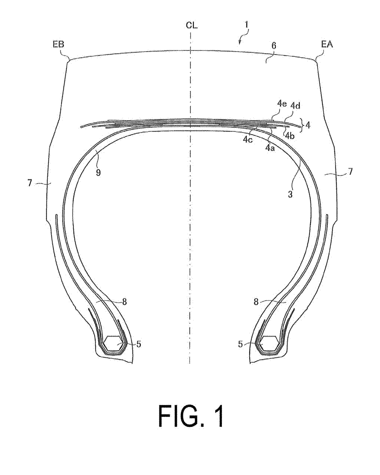
Tire structural factors that cause deterioration in durability include disturbance in carcass cords near an end of a belt portion and fluctuation in an interval between the carcass cords (corrugation).
As a result, the carcass cords in a carcass ply are pulled along with a flow of the tread rubber, causing disturbance and corrugation in the carcass cords near the end of the belt portion.
However, the method described above is a method for suppressing corrug
Method used
View moreImage
Smart ImageViewing Examples

Examples
 PUM
| Property | Measurement | Unit |
|---|---|---|
| Fraction | aaaaa | aaaaa |
| Fraction | aaaaa | aaaaa |
| Angle | aaaaa | aaaaa |
Abstract
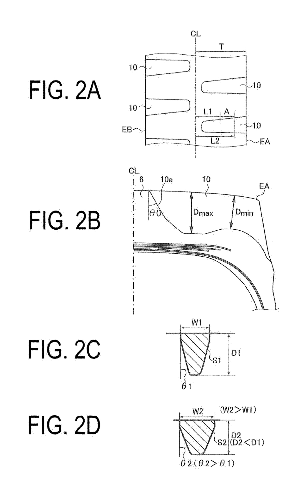
A pneumatic tire includes a tread portion with shoulder lug grooves spaced apart in a circumferential direction, each extending outward in a tire lateral direction, opening to a ground contact end, and including a closed end inward in the tire lateral direction. In a region of each of the shoulder lug grooves from an end of a belt having a greatest width in a belt portion of the pneumatic tire to an inner side in the tire lateral direction, the shoulder lug groove has a groove width that decreases inward in the tire lateral direction, and includes a portion where a groove cross-sectional area is kept constant by a change in at least one of a groove wall angle or a groove depth of the shoulder lug groove, the portion being provided in the tire lateral direction across a length of at least 20% of half a tire development width.
Description
Login to view more Claims
Login to view more Application Information
Patent Timeline
 Owner YOKOHAMA RUBBER CO LTD
- R&D Engineer
- R&D Manager
- IP Professional
Why Eureka
- Industry Leading Data Capabilities
- Powerful AI technology
- Patent DNA Extraction
Try Eureka
Browse by: Latest US Patents, China's latest patents, Technical Efficacy Thesaurus, Application Domain, Technology Topic.
© 2024 PatSnap. All rights reserved.Legal|Privacy policy|Modern Slavery Act Transparency Statement|Sitemap