Detachable computer mouse

a mouse and mouse body technology, applied in the field of mouse, can solve the problems of trouble for hardcore game players, affecting the performance of the mouse, and being unable to adjust the mouse position,

Active Publication Date: 2019-02-28
DEXIN ELECTRONICS LTD +1
View PDF2 Cites 2 Cited by
  • Summary
  • Abstract
  • Description
  • Claims
  • Application Information

AI Technical Summary

Benefits of technology

The technical effect of this invention is to create a removable computer mouse that overcomes problems with existing mice.

Problems solved by technology

The technical problem addressed in this patent text relates to improving the design of removable computer mice without sacrificing functionality or causing difficulties during play sessions. This is because current designs allow for limited numbers of side button configurations, which makes it difficult for hardcore gaming players to operate these mice properly.

Method used


Image

  • Detachable computer mouse
  • Detachable computer mouse
  • Detachable computer mouse

Examples


Embodiment Construction

[0018]The aforementioned illustrations and following detailed descriptions are exemplary for the purpose of further explaining the scope of the instant disclosure. Other objectives and advantages related to the instant disclosure will be illustrated in the subsequent descriptions and appended drawings.

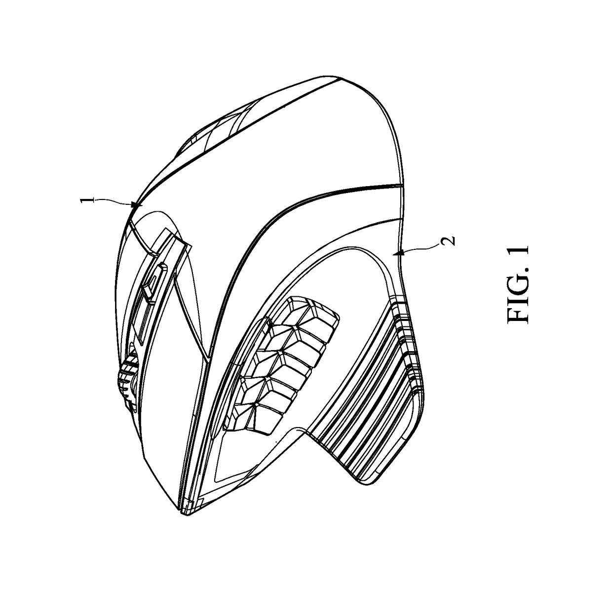
[0019]Referring to FIGS. 1 through 9, the detachable computer mouse in accordance with the present disclosure mainly has a mouse body 1 and a detachable input module 2.

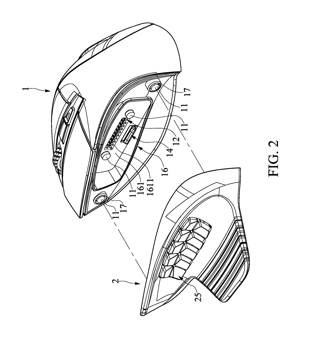
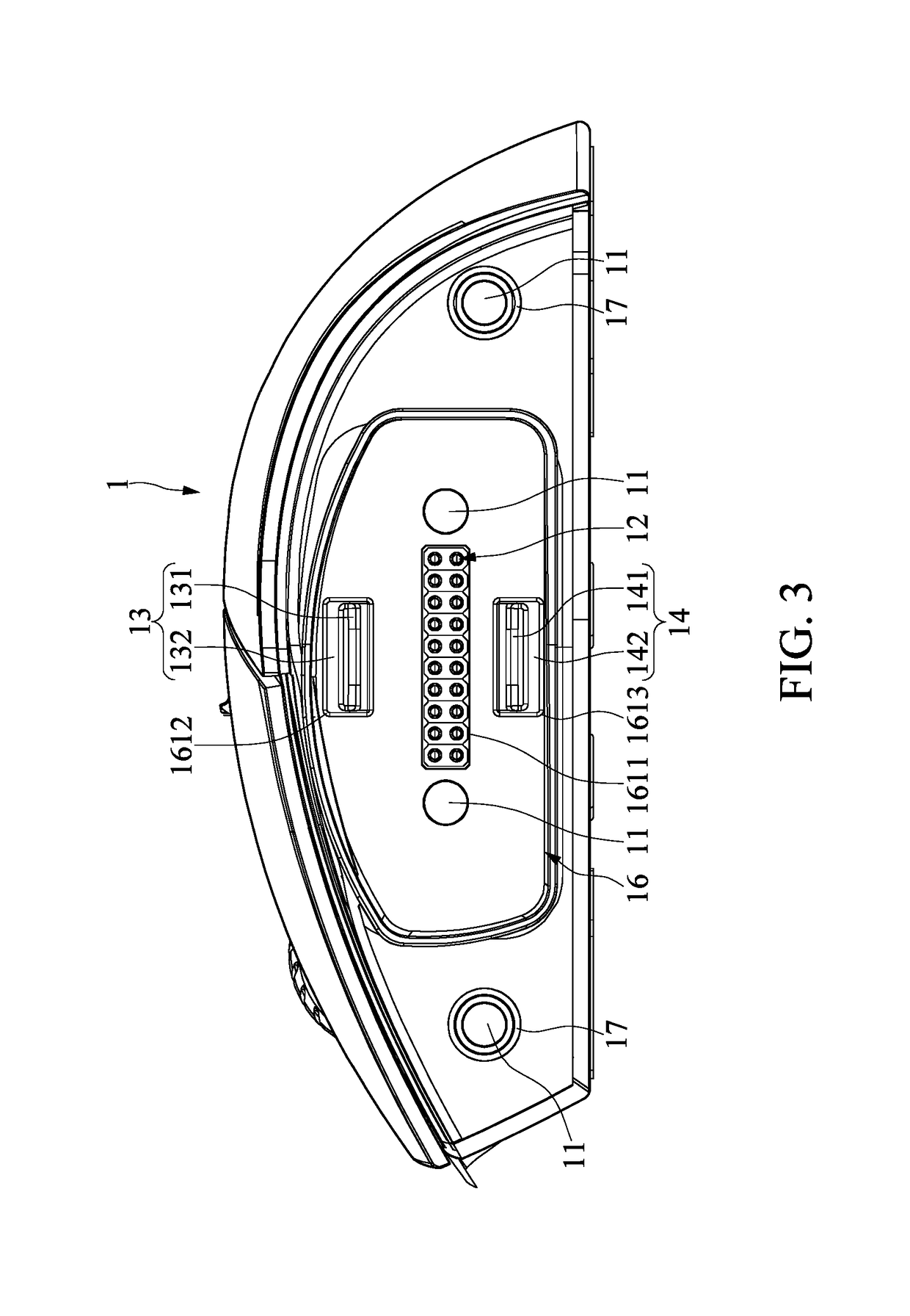
[0020]As shown in FIG. 2 and FIG. 3, one side of the mouse body 1 is provided with a plurality of first magnetic members 11, a pogo-pin assembly 12, a first snap-fit member 13 and a second snap-fit member 14. In this embodiment, one side of the mouse body 1 may be the left side of the mouse body 1. In other embodiments, the one side of the mouse body 1 may be the right side of the mouse body 1 for a left-handed operator.

[0021]Further, as shown in FIG. 4 and FIG. 5, one side of the detachable input module 2 is provided with


PUM


Abstract

A detachable computer mouse includes a mouse body and a detachable input module. The mouse body is provided with a plurality of first magnetic members, a pogo-pin assembly, a first snap-fit member and a second snap-fit member. The detachable input module is provided with a plurality of second magnetic members, a metal pad assembly, a first hook and a second hook, and a plurality of function buttons. The first magnetic members are correspondingly and magnetically adhered with the second magnetic members, the pogo-pin assembly is correspondingly in direct contact with the metal pad assembly, and the first snap-fit member and the second snap-fit member are respectively elastically snap-fitted to the first hook and the second hook when the detachable input module is coupled to the mouse body.

Description


Claims


Application Information

Patent Timeline
Owner DEXIN ELECTRONICS LTD
Why Eureka
Try Eureka