Method and device for determining the depth of a crack in a solid
a solid depth and depth technology, applied in the field of structures for detecting cracks, can solve the problems of inability to automate, no non-destructive quantitative method allowing the depth of a solid to be determined, and high cost of consumable use, so as to increase the robustness of the method and reduce the possible difference in distance between the heated area and the crack.
- Summary
- Abstract
- Description
- Claims
- Application Information
AI Technical Summary
Benefits of technology
Problems solved by technology
Method used
Image

Examples
Embodiment Construction
OF REALIZATION OF THE INVENTION
[0070]The present description is given in a non-limiting way, each characteristic of an embodiment being able to be combined with any other characteristic of any other embodiment in an advantageous way.
[0071]It is now noted that the figures are not to scale.
[0072]“Phase” refers to a delay in the propagation of heat within a solid.
[0073]“Terminal” refers to any device comprising a computing unit. Here, “terminal” means, for example:[0074]a computer;[0075]a digital tablet;[0076]a smartphone; or[0077]a server.
[0078]The general observation forming the basis of the present invention is the following:
[0079]A crack located in a heat diffusion area of a heat source positioned at the surface of a solid acts as a barrier altering the diffusion of the heat. The heat diffusion is also altered as a function of the duration of the heating of the surface of the solid. Therefore, for a continuous thermal excitation traversing a path parallel to the general direction of t
PUM
 Abstract
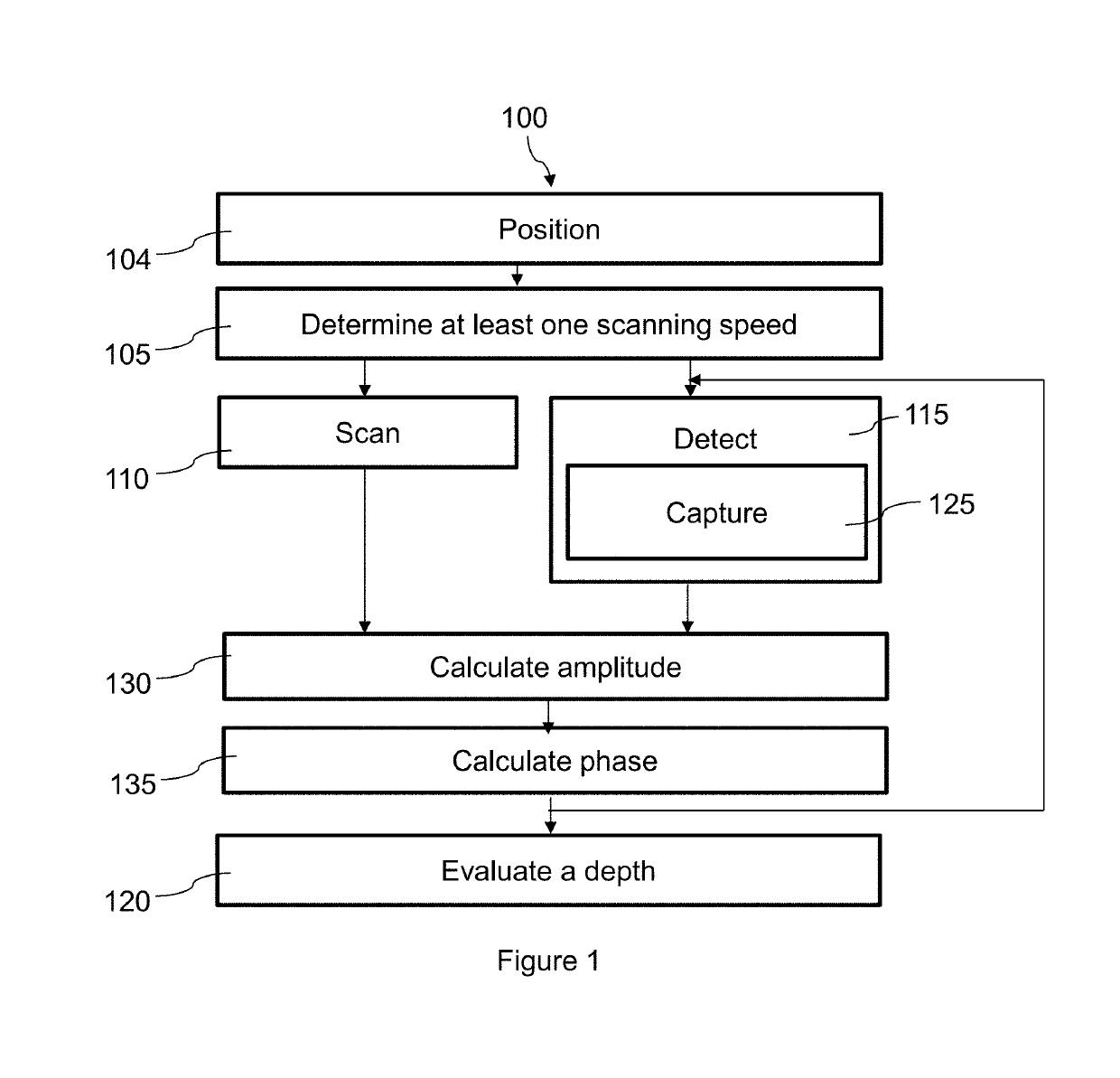
- a step (105) of determining at least one speed for scanning a surface of the solid comprising the crack by a positioned heat source;
- for every speed determined:
- a step (110) of scanning a portion of the surface of the solid, parallel to the general direction of the crack, by the heat source at said speed; and
- a step (115), synchronous with the scanning step, of detecting at least one value of a physical quantity representing the local heating of the surface of the scanned solid; and
Description
Claims
Application Information
 - R&D Engineer
- R&D Manager
- IP Professional
- Industry Leading Data Capabilities
- Powerful AI technology
- Patent DNA Extraction
Browse by: Latest US Patents, China's latest patents, Technical Efficacy Thesaurus, Application Domain, Technology Topic.
© 2024 PatSnap. All rights reserved.Legal|Privacy policy|Modern Slavery Act Transparency Statement|Sitemap