Catalytic converter with electrically heatable heating plate

Active Publication Date: 2019-12-19
VITESCO TECH GMBH
View PDF6 Cites 1 Cited by
  • Summary
  • Abstract
  • Description
  • Claims
  • Application Information

AI Technical Summary

Benefits of technology

[0025]It is also expedient if the current path is partially subdivided into at least two mutually separated current paths by the insulating intermediate layer. This is particularly advantageous in order for example to be able to better guide the current flow in critical regions. This particularly makes it possible to avoid hotspots which may arise as a result of excessive heating on account of a locally high current flow. Since the current seeks the path of least resistance, such hotspots may occur particularly at kink points and tight bends in the region of the inner smaller bend radii, since the current does not flow uniformly over the whole width of the current path, but a greater current flow occurs in the region of the tighter bending radii.
[0026]The current flow is influenced in a targeted manner by an insulating intermediate layer, with the result that such a nonuniform distribution may be avoided or at least significantly reduced. This is advantageous in order to achieve more homogeneous heating of the heating plate.
[0027]Moreover, it is advantageous if the insulating intermediate layer itself or the insulating layer on the intermediate layer has a shorter extent than t

Problems solved by technology

If the entire honeycomb structure generated by the winding operation were a completely electrically conducting interconnected region, the current conduction through the honeycomb structure would occur arbitrarily and randomly as it were, and therefore t

Method used


Image

  • Catalytic converter with electrically heatable heating plate
  • Catalytic converter with electrically heatable heating plate
  • Catalytic converter with electrically heatable heating plate

Examples


Embodiment Construction

[0039]The following description of the preferred embodiment(s) is merely exemplary in nature and is in no way intended to limit the invention, its application, or uses.

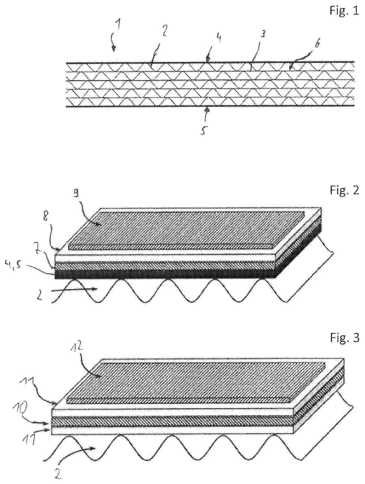
[0040]FIG. 1 shows a sectional view through a layer stack 1. The layer stack 1 is formed from a plurality of corrugated metal foils 2 and a plurality of smooth metal foils 3 which are stacked on top of one another in alternating fashion. A plurality of flow ducts 6 through which exhaust gas may flow are formed between the metal foils 2, 3. The metal foils 2, 3 shown in FIG. 1 are by way of example and do not limit the choice of the metal foils.

[0041]The upper edge layer 4 and the lower edge layer 5 are both formed by smooth metal foils 3. On their respective outer sides, they have an insulating layer which electrically insulates the layer stack to the top and bottom. For this purpose, an electrically insulating material is applied for example to the edge layers 4, 5.

[0042]FIG. 2 shows a detail view of one of the edge lay


PUM


Abstract

A catalytic converter having a honeycomb structure for the aftertreatment of exhaust gases of an internal combustion engine and having an electrically heatable heating plate, wherein the heating plate is formed from a plurality of metal foils which are stacked on top of one another to form a layer stack and are finally wound to form a honeycomb structure having a plurality of flow ducts, wherein the heating plate has arranged therein an insulating means via which electrical insulation is formed between at least two mutually adjacently arranged wound metal foils.

Description


Claims


Application Information

Patent Timeline
Owner VITESCO TECH GMBH
Why Eureka
Try Eureka