MEMS frequency-tuning springs

a technology of frequency tuning and springs, applied in the field of microelectromechanical systems, can solve the problems of reducing the effective spring constant associated with oscillation mode, reducing the resonant frequency, and the practical tuning range is quite limited in parallel-plate configurations

Active Publication Date: 2020-03-26
MURATA MFG CO LTD
View PDF0 Cites 0 Cited by
  • Summary
  • Abstract
  • Description
  • Claims
  • Application Information

AI Technical Summary

Benefits of technology

The invention relates to an apparatus for adjusting frequencies by adding special electrical elements onto certain parts or structures called spring-mass systems. These devices are designed with specific movements caused when they vibrate up and down repeatedly over time. This allows them to generate different levels of resistance at each position within their range of motion. By doing this, it becomes possible to control how fast these components move around inside buildings like cars without affecting their overall functionality.

Problems solved by technology

Technical Problem: In order to achieve consistency in performance across different types of electronic devices while reducing production variations caused by imperfections during fabrications processes like wafer bonding and packaging. To address this problem, there have been proposed various techniques involving varying the electrical characteristics of individual parts called inductors, resistive materials, varactile structures, etc., but it has proven hard to find ways to ensure consistently high quality results despite changes made throughout their lifetimes.

Method used


Image

  • MEMS frequency-tuning springs
  • MEMS frequency-tuning springs
  • MEMS frequency-tuning springs

Examples


Embodiment Construction

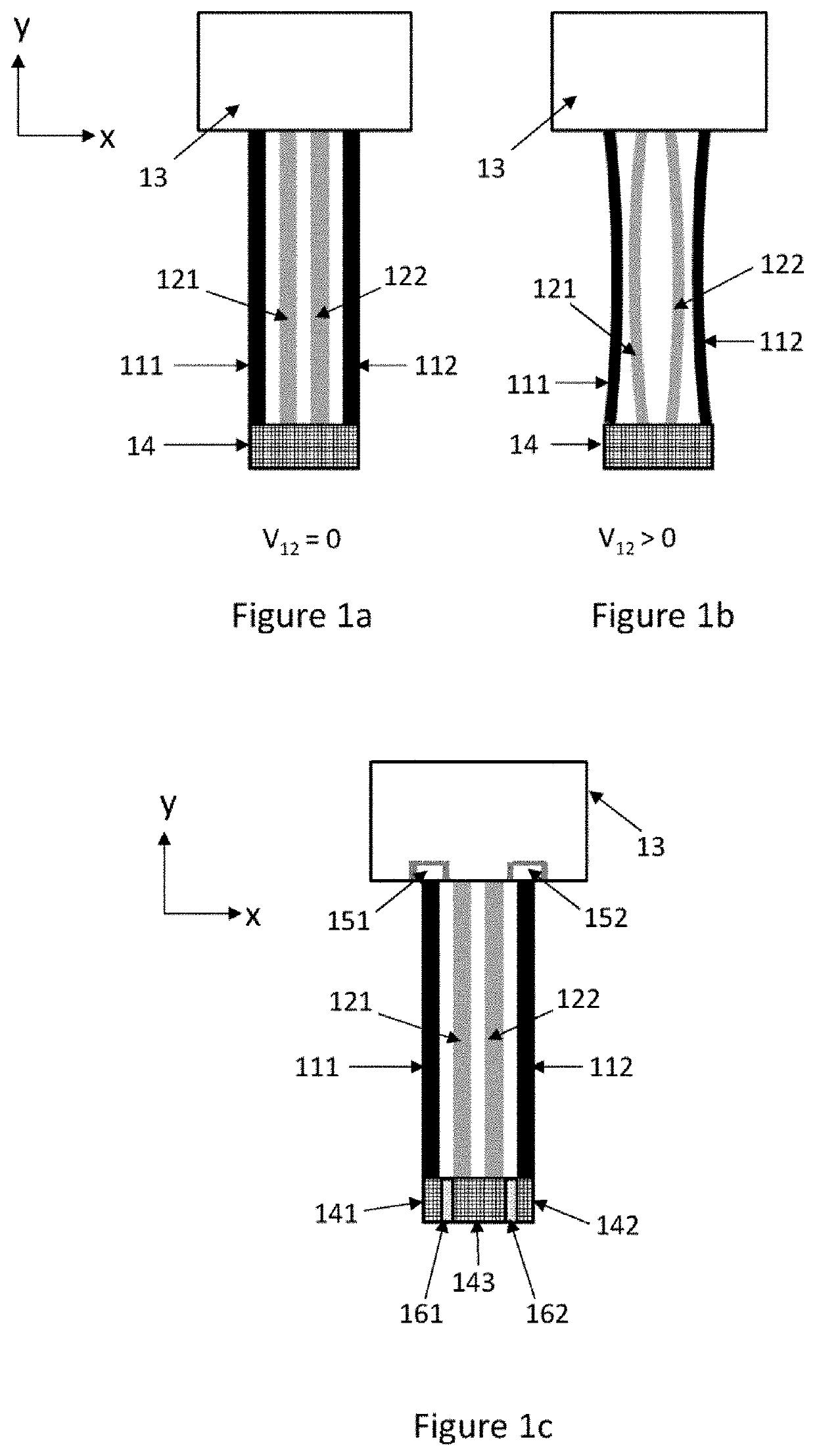
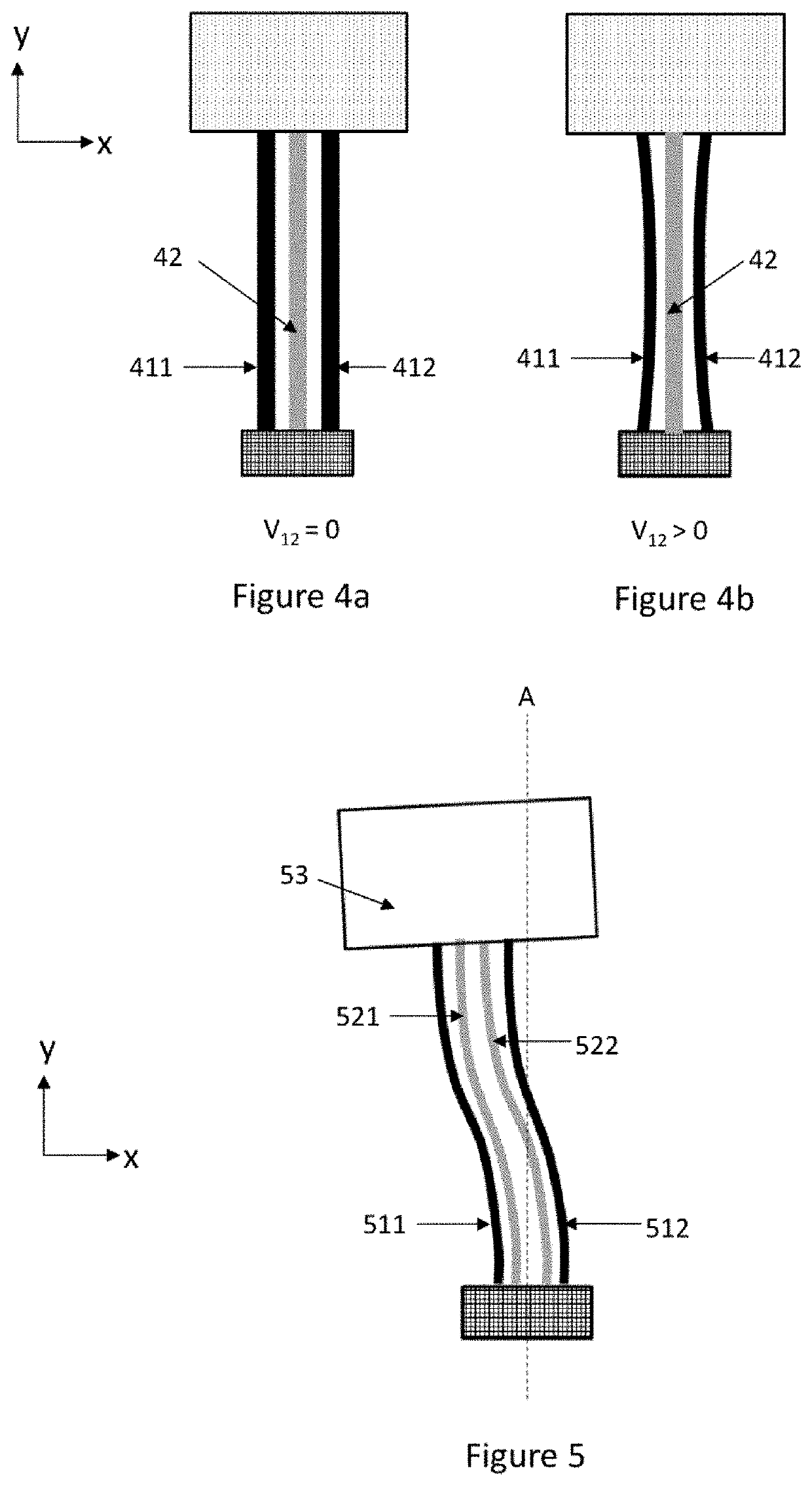
[0021]This disclosure describes a microelectromechanical system that comprises a fixed support, at least one partly mobile mass element which is suspended from the fixed support by one or more suspension units, and at least one drive transducer which is configured to set the partly mobile mass element in resonance oscillation at a resonance frequency. Each suspension unit comprises one or more first springs which extend from the fixed support to the partly mobile mass element. Each suspension unit also comprises one or more second springs, and each second spring extends from the fixed support to the partly mobile mass element substantially parallel and adjacent to one first spring. The one or more first springs are electrically isolated from the one or more second springs, and the microelectromechanical system further comprises a voltage source configured to apply a frequency tuning voltage between the one or more first springs and the one or more second springs.

[0022]A corresponding m


PUM


Abstract

A microelectromechanical system with at least one partly mobile mass element which is suspended from a fixed support by one or more suspension units. Each suspension unit comprises first springs which extend from the fixed support to the partly mobile mass element, and second springs which also extend from the fixed support to the partly mobile mass element. Each second spring is substantially parallel and adjacent to one first spring. The first springs are electrically isolated from the second springs, and the microelectromechanical system comprises a voltage source configured to apply a frequency tuning voltage between the one or more first springs and the one or more second springs.

Description


Claims


Application Information

Patent Timeline
Owner MURATA MFG CO LTD
Why Eureka
Try Eureka