Method for toe variable control of a rear wheel steering system

Active Publication Date: 2020-04-09
HYUNDAI MOTOR CO LTD +1
View PDF0 Cites 0 Cited by
  • Summary
  • Abstract
  • Description
  • Claims
  • Application Information

AI Technical Summary

Benefits of technology

[0023]First, it is possible to enhance RWS performance by the toe change linearization for each bump/rebound caused by the suspension geometry of the vehicle. Second, it is possible to greatly enhance handling/agility/stability through additional toe adjustment of the rear wheel reflecting the bump and the rebound. Third, it is possible to enhance the limited cornering ability of the vehicle by increasing the toe control amount during handling through the smooth weight transfer that weakly changes the bump/rebound. Fourth, it is possible to compensate for a sudde

Problems solved by technology

Thus, it is difficult to maintain the toe linearization control effect when a relatively big change in the bump/rebound occurs.
This is because, in vehicle suspensions, bump and rebound caused by geometry can bring not only a sudden speed change due to a berm or a pothole during handling, but also a speed change due to handling weight transfer during handling in a flat area.
The sudden speed change of the bump and rebound and the speed change due to the handling weight transfer can cause a change in the weight on the ground surface of a tire that is important for handling.
Thus, an action of a lateral force of the rear wheel is suddenly increa

Method used


Image

  • Method for toe variable control of a rear wheel steering system
  • Method for toe variable control of a rear wheel steering system
  • Method for toe variable control of a rear wheel steering system

Examples


Embodiment Construction

[0029]Hereinafter, embodiments of the present disclosure are described in detail with reference to the accompanying drawings. The embodiments can be embodied by those having ordinary skill in the art to which the present disclosure pertains in various different forms as an example, such that it is not limited to the embodiments described herein.

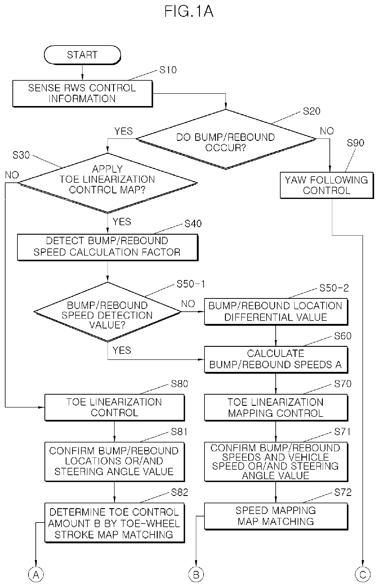
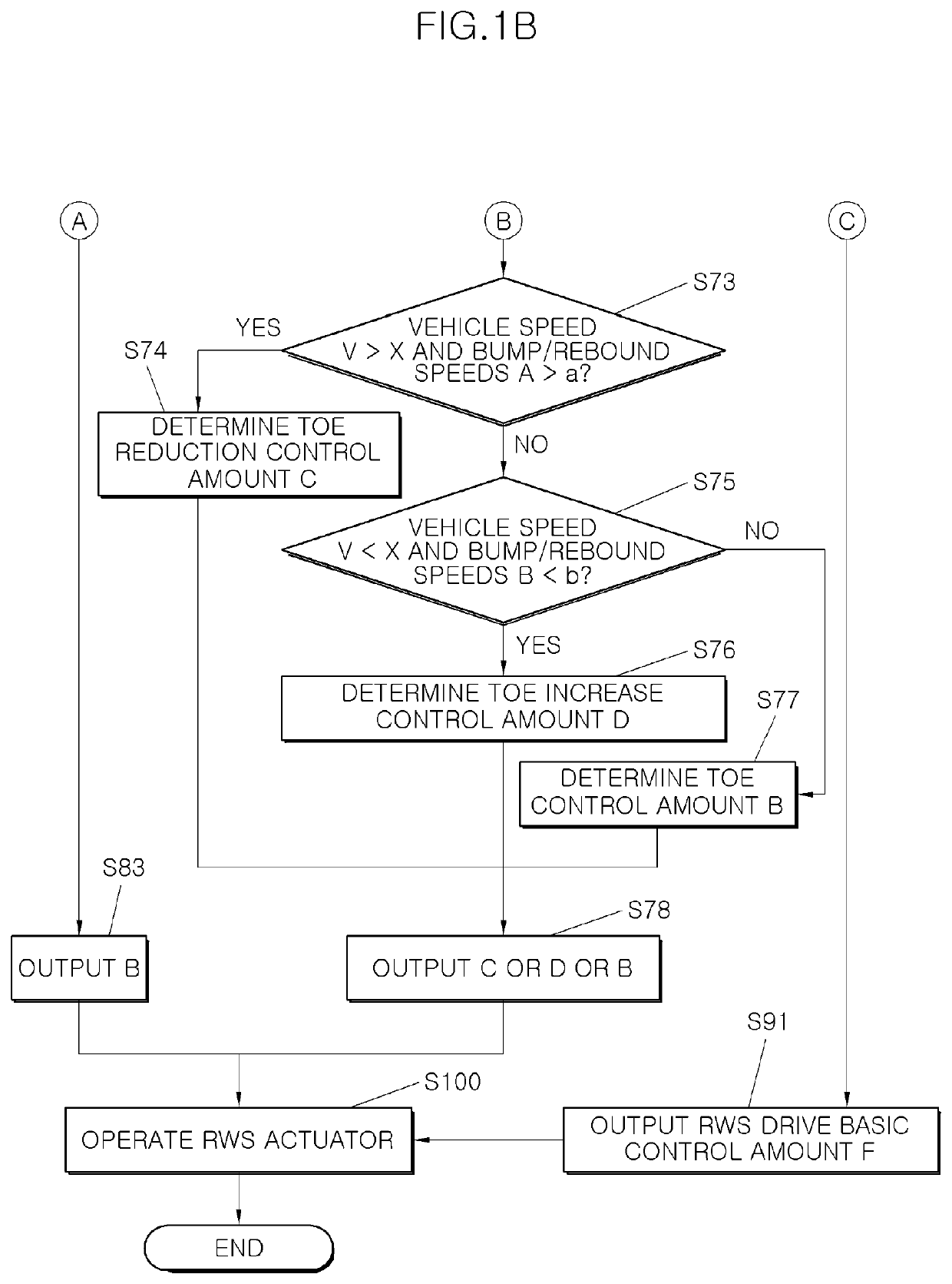
[0030]Referring to FIGS. 1A and 1B, a control system to perform a toe variable control method is classified into a yaw-following control S90, a toe linearization mapping control S70-S78, or a toe linearization control S80. In a yaw-following control S90, a Rear Wheel Steering (RWS) actuator operation [S100] is performed by a RWS drive basic control amount F [S91] as in the conventional method by detecting RWS control information [S10] and then confirming occurrence of bump / rebound [S20]. In a toe linearization mapping control [S70]˜[S78], the RWS actuator operation [S100] is performed by toe reduction / increase after determining whether or no


PUM


Abstract

A toe variable control method includes a toe linearization mapping control in which a toe control is switched from a constant control amount to a variable control amount in a rear wheel steering system by bump/rebound speeds of a bump and a rebound becoming a variable when the bump and rebound of a wheel are detected by a controller.

Description


Claims


Application Information

Patent Timeline
Owner HYUNDAI MOTOR CO LTD
Why Eureka
Try Eureka