Hydraulic Ball Guide For Subsurface Ball Valves

a technology of ball valves and hydraulic guides, which is applied in the direction of sealing/packing, positive displacement liquid engines, and well accessories. it can solve the problems of tens of thousands and/or hundreds of thousands of dollars lost, severe damage to the valve,

Active Publication Date: 2020-05-07
RICH JERRY
View PDF7 Cites 0 Cited by
  • Summary
  • Abstract
  • Description
  • Claims
  • Application Information

AI Technical Summary

Benefits of technology

The technical effect of this innovation is that it improves how well a piston can move when there are changes or fluctuations in pressure caused by changing conditions such as temperature variations during operation.

Problems solved by technology

This patented technical solution describes improving a type called a new version of a conventional ball valvelayer device. It involves adding extra elements like pipelines or rods along with a specialized tool set designed specifically for handling oilfield products such as crude oil and refined hydrocarbon gases. These added tools help control liquid movement throughout the process while also reducing stress caused by rubbing contact between the balls and their respective valve housings. Additionally, there may exist variations where older versions of existing devices were modified without affecting functionality. Overall, this innovation helps improve efficiency and reliance of the overall operation of the traditional valved system described earlier in the field.

Method used


Image

  • Hydraulic Ball Guide For Subsurface Ball Valves
  • Hydraulic Ball Guide For Subsurface Ball Valves
  • Hydraulic Ball Guide For Subsurface Ball Valves

Examples


Embodiment Construction

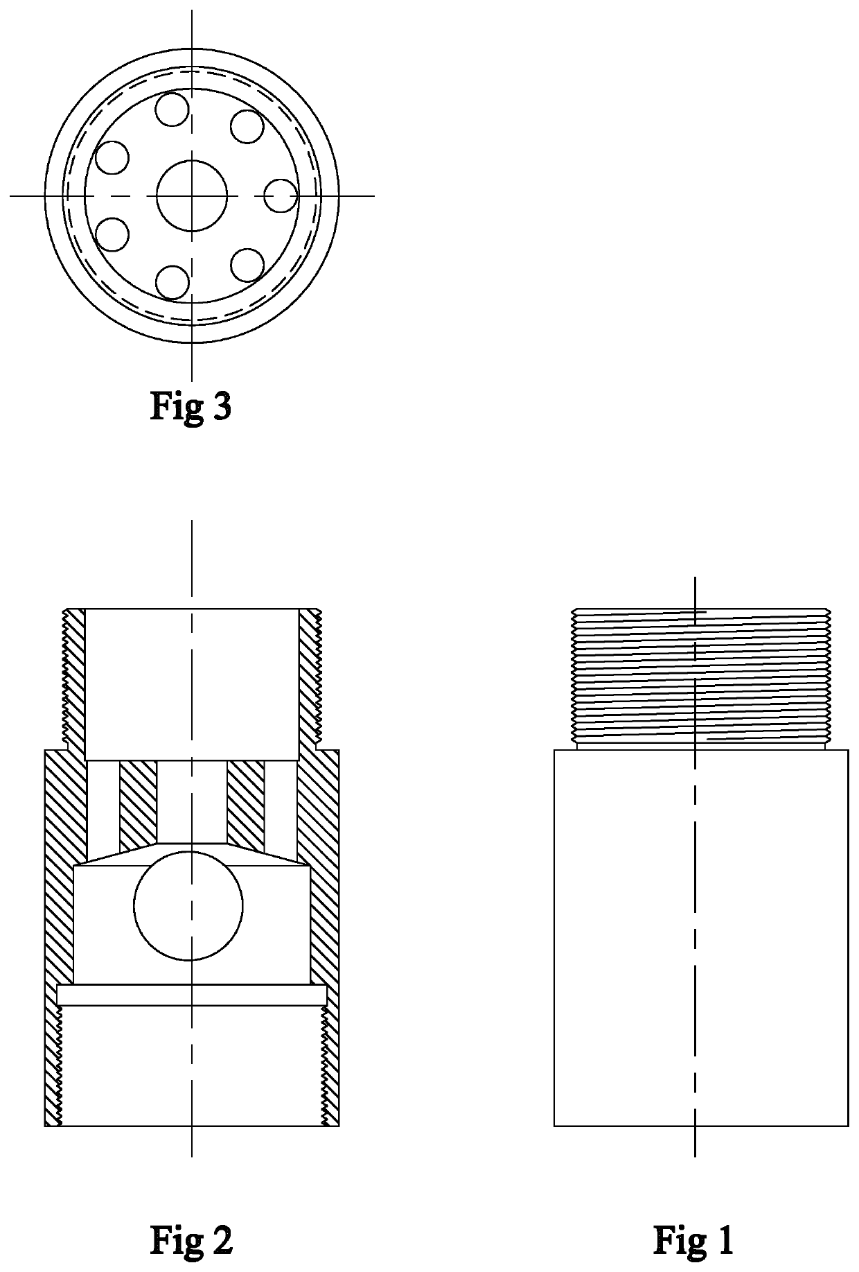
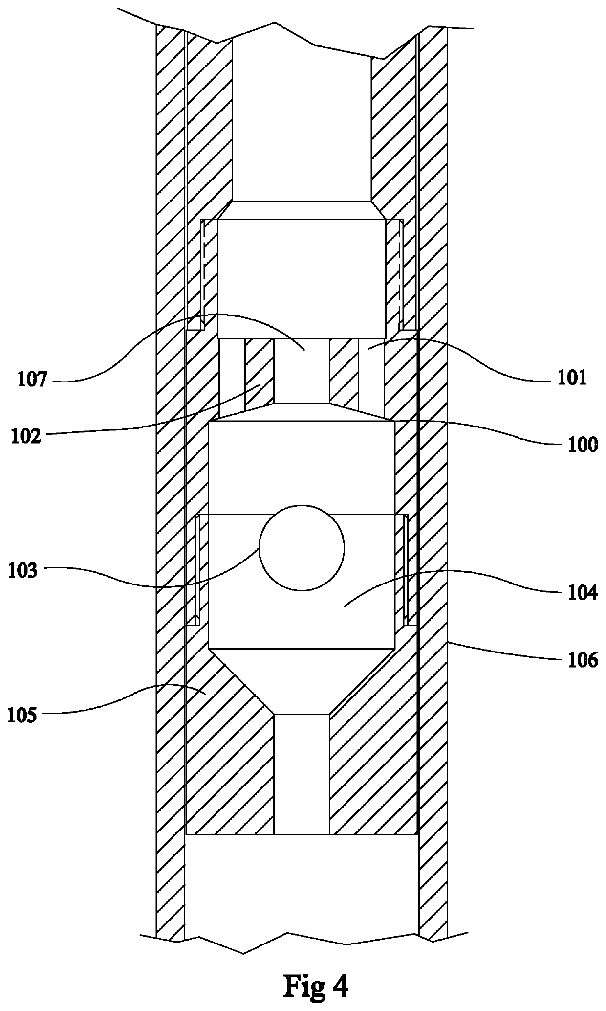
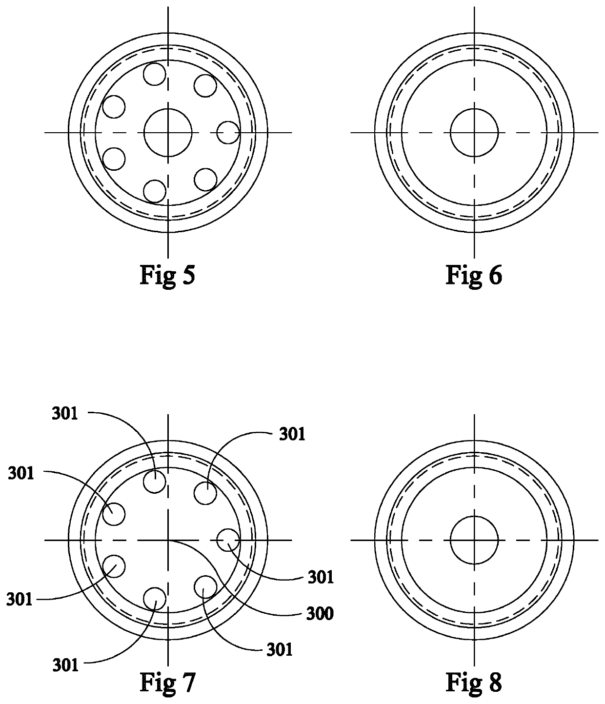
[0026]In reference to FIG. 9, on upstroke of a pump system 20, a traveling ball valve 21 is disposed on the lower end of a plunger 23 engaging a sucker rod string 24. During upstroke, well fluid pressure seats the ball 25 of the traveling ball valve 21 against a seat plug 26 resulting from well fluid pressure created by the pump action of the pump system 20. During upstroke, an upper axial port 29 is open while a lower axial port 27 is closed when fluid pressure seats the ball 25 against the seat plug 26 preventing well fluids from flowing up through the lower axial port 27 and into the traveling ball valve chamber 28.

[0027]On downstroke, as referenced in FIG. 10, the ball 25 of the traveling ball valve 21 is unseated from the seat plug 26 because of hydraulic pressure resulting from the pump action of the pump system flowing up from the lower axial port 27, which pushes the ball 25 against a ball seat 31. During downstroke, well fluid pressure being forced up through the axial port 27


PUM


Abstract

An improved ball valve on a pump system comprising a ball valve having a ball, a first end arranged for operatively engaging the pump system, a first axial port on the first end sufficiently narrow to prevent the passage of the ball, a ball-seat disposed on the first end with a plurality of ports annularly disposed around the ball and extending through the ball-seat, a second axial port on a second end sufficiently narrow to prevent the passage of the ball, and the second end of the ball valve arranged for connecting to the pump system. The improved ball valve further comprising a ball seat without a first axial port. The improved ball valve further comprising a plurality of ports extending outwardly from the first axial port and extending through the ball-seat.

Description


Claims


Application Information

Patent Timeline
Owner RICH JERRY
Why Eureka
Try Eureka