Active composite variable damping rotational control device

a control device and composite variable technology, applied in the direction of spring/damper functional characteristics, shock absorption, shock proofing, etc., can solve the problems of low control efficiency, almost useless to control the torsional swing, and weakening the control effect and even completely losing the function, etc., to achieve greater robustness

Active Publication Date: 2020-11-12
QINGDAO TECHNOLOGICAL UNIVERSITY
View PDF0 Cites 1 Cited by
  • Summary
  • Abstract
  • Description
  • Claims
  • Application Information

AI Technical Summary

Benefits of technology

This new type of controller can adjust its behavior more effectively without being influenced from changes made on it's structure or outside loads like rainwater pressure.

Problems solved by technology

The technical problem addressed in this patented text relates to improving the performance of vibration reduction systems used in vehicles due to their potential impact upon surrounding objects when they are subjected to severe conditions. Existing solutions involve adding weight to prevent excess movement while still allowing certain parts of these structures to rotate around without causing harm. This approach requires heavy equipment installation and maintenance costs, which limit its usefulness. There exists another solution called Active Control System(ACS). ACSS uses feedback signals obtained through sensors attached directly onto surfaces inside the structure's interior to determine if there should move away or stay within acceptable limits. It achieves this objective by actively reducing unwanted movements induced by gravit fields and other factors affecting the behavior of the controlled object.

Method used


Image

  • Active composite variable damping rotational control device
  • Active composite variable damping rotational control device
  • Active composite variable damping rotational control device

Examples


Embodiment Construction

[0027]The present invention is further described below in combination with the accompanying drawings.

[0028]In the present embodiment, a structure with a simple pendulum structure model as a basic mechanical model prototype is taken as an example.

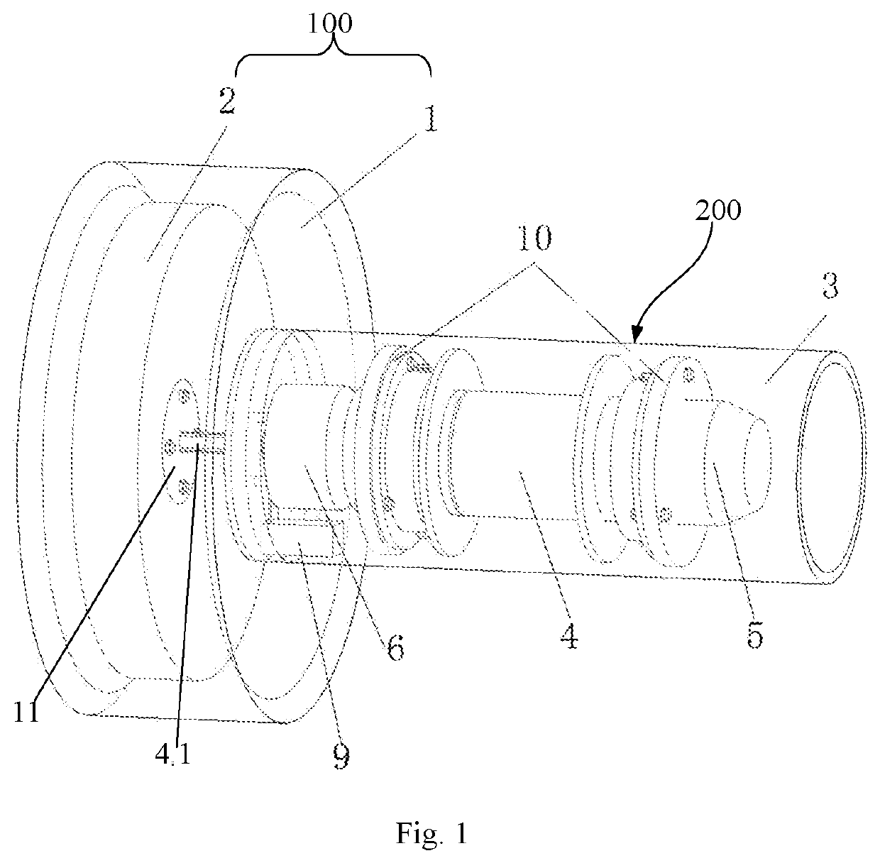
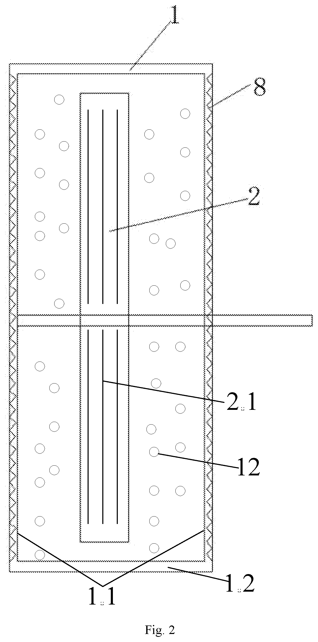
[0029]As shown in FIGS. 1-3, an active composite variable damping rotational control device of the present invention includes a variable damping module 100 and a power module 200. The variable damping module 100 includes a magnetorheological fluid tank 1 and a rotational inertia wheel 2. The power module 200 includes a device tubular cavity 3, and a driver 4, an encoder 5 and a speed changer 6 which are fixed in the device tubular cavity 3. The device tubular cavity 3 is connected with a controlled structure 7. The rotational inertia wheel 2 is parallel to a surface of the controlled structure 7 that is subjected to the torsional swing.

[0030]The magnetorheological fluid tank 1 is a round tubular shape. Two circular end surfaces 1.1 and a cylind


PUM


Abstract

An active composite variable damping rotational control device includes a variable damping module and a power module. The variable damping module includes a magnetorheological fluid tank and a rotational inertia wheel. The rotational inertia wheel is arranged in the magnetorheological fluid tank fully filled with magneorheological fluid. The power module includes a device tubular cavity, a driver, an encoder and a speed changer. The driver is fixed on the inner wall of the device tubular cavity. The driver, the encoder and the speed changer are coaxial. A driving shaft of the driver passes through the speed changer and extends into the magnetorheological fluid tank to be fixed perpendicularly at the center of the rotational inertia wheel. The control effect of the present invention may not be greatly affected by the change of a structural form and the change of an external load.

Description


Claims


Application Information

Patent Timeline
Owner QINGDAO TECHNOLOGICAL UNIVERSITY
Why Eureka
Try Eureka