Method for calibrating a gyrometer equipping a vehicle
- Summary
- Abstract
- Description
- Claims
- Application Information
AI Technical Summary
Problems solved by technology
Method used
Image

Examples
first embodiment
[0095]Generally speaking, said parameter representative of an error on the calibration parameters is a function of at least said second estimated angular velocity, calculated for the determined values of the calibration parameters, and a “reference” angular velocity illustrating a comparison element, which is the value of the first angular velocity (the gyrometric angular velocity).
[0096]This first embodiment of step (c) is called intrinsic since it only uses quantities available in step (b). Preferably, the estimation residues of step (b) are used, i.e. in the odometric case said parameter representative of an error is in particular the norm (e.g. L2 or L∞) of ωodo(estimation)−ωgyro(estimation) over a given time interval. In such a case, step (c) may be implemented in a concomitant manner with step (b). In the case of a recursive filter, it is possible to use the norm (e.g. L2 or L∞) of the innovation of the filter over a given time period.
second embodiment
[0097]In step (c), called extrinsic, quantities of yet another type are used, in particular:[0098]the steering wheel angle, if odometry has been used[0099]odometry, if the steering wheel angle has been used,[0100]GNSS data, e.g. GPS, (if / when available),[0101]etc.
[0102]Those skilled in the art will know how to calculate on the basis of one or the other of these quantities a reference angular velocity, so as to compare it with the second estimated angular velocity.
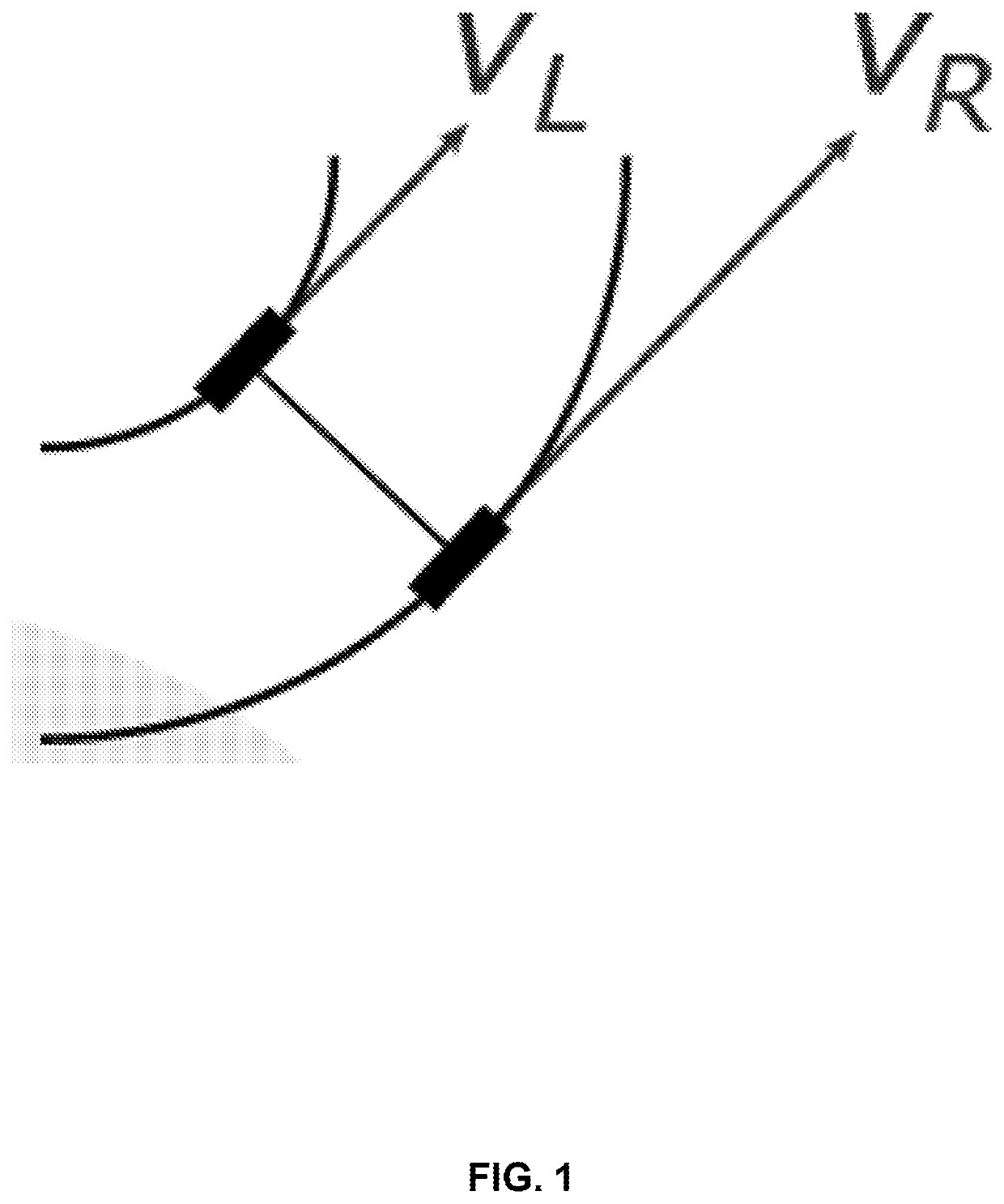
[0103]It should be noted that said theoretical angular velocity may be obtained using odometric information of optional wheels not used at step (b), i.e. step (a) comprises, for at least one additional wheel provided with an odometer, the acquisition by this odometer of a measured velocity of the additional wheel, so as to obtain a third estimated angular velocity ωodo′(estimation) in a similar manner to the second (wheels are just changed, to note that a wheel used for the first angular velocity may be reused for the third
PUM
 Abstract
- (a) Acquisition
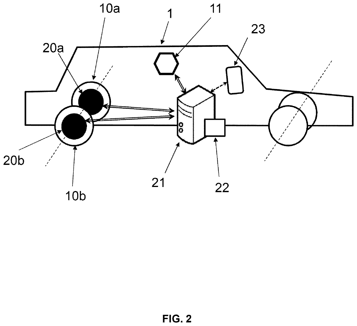
- by the gyrometer (11), of a measured angular velocity of the vehicle (1), and
- by means for measuring (20) at least one quantity representative of the angular velocity of the vehicle (1), of measured values of said at least one quantity representative of the angular velocity of the vehicle (1);
- (b) Determination by data processing means (21) of values of at least one parameter for calibrating the gyrometer (11) minimising a difference between a first estimated angular velocity of the vehicle (1) and a second estimated angular velocity of the vehicle (1),
- the first estimated angular velocity of the vehicle (1) being a function of the measured angular velocity and parameters for calibrating the gyrometer (11), and
- the second estimated angular velocity of the vehicle (1) being a function of the measured values of said at least one quantity representative of the angular velocity of the vehicle (1).
- (a) Acquisition
Description
Claims
Application Information
 - R&D Engineer
- R&D Manager
- IP Professional
- Industry Leading Data Capabilities
- Powerful AI technology
- Patent DNA Extraction
Browse by: Latest US Patents, China's latest patents, Technical Efficacy Thesaurus, Application Domain, Technology Topic.
© 2024 PatSnap. All rights reserved.Legal|Privacy policy|Modern Slavery Act Transparency Statement|Sitemap