Multi-rail express transit system

a transit system and express technology, applied in the direction of railway tracks, carriages, wagons/vans, etc., can solve the problems of increasing the travel time, speed limit, and large and highly populated cities of the world would face significant traffic problems and air pollution

Active Publication Date: 2021-06-03
SHIRVANI MANSOUR +1
View PDF0 Cites 0 Cited by
  • Summary
  • Abstract
  • Description
  • Claims
  • Application Information

AI Technical Summary

Benefits of technology

The invention relates to a transportation system that allows people to easily move around while they are on their way from one location to another. This makes it faster than traditional methods like stopping or getting off buses.

Problems solved by technology

The technical problem addressed by this patent is how to improve the efficiency of delivering passengers between different locations on a single train line while also reducing emissions from station stops caused by traffic jams. Current solutions are slow and require frequent stops for passengers, making it difficult to meet growing needs.

Method used


Image

  • Multi-rail express transit system
  • Multi-rail express transit system
  • Multi-rail express transit system

Examples


Embodiment Construction

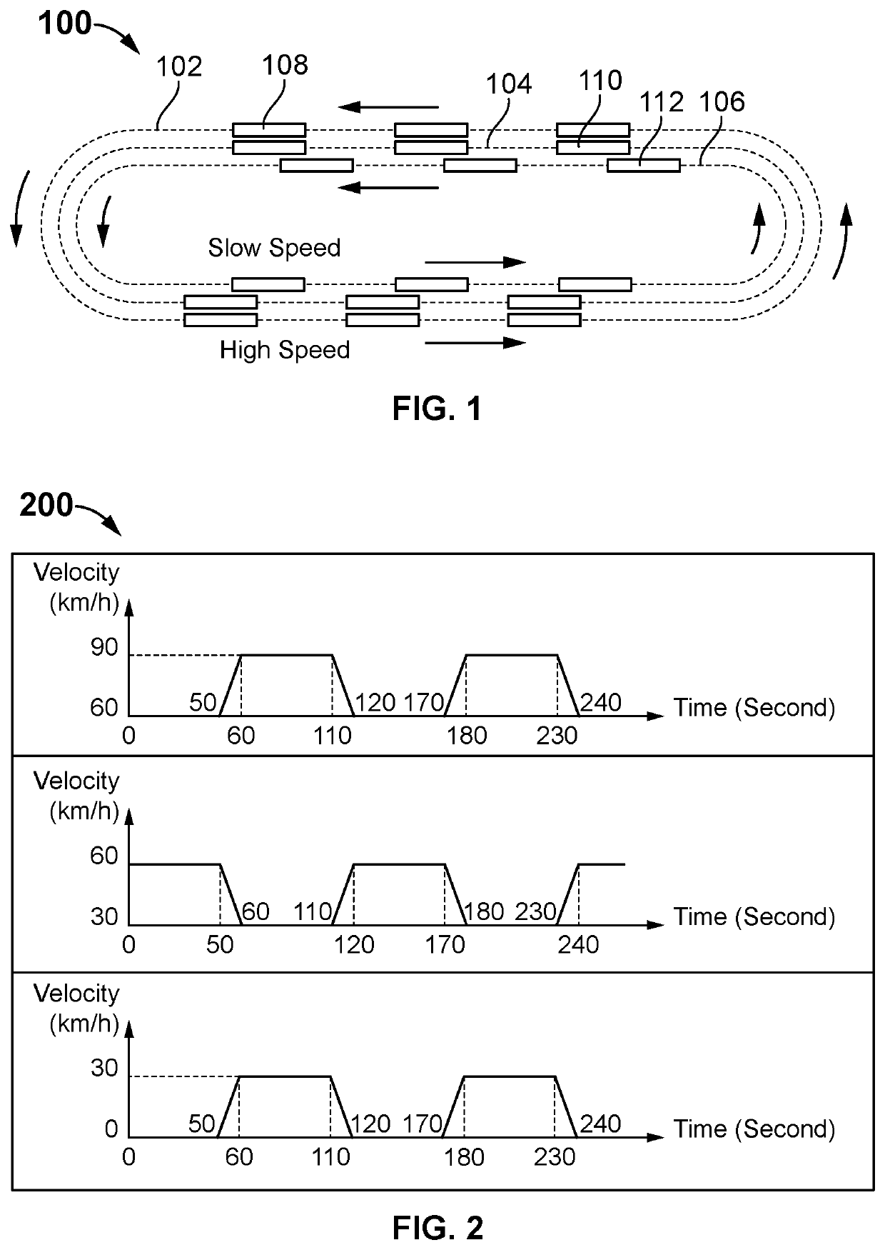
[0031]The present invention generally relates to a rail transit system and more particularly relates to a multi-rail express transit system for allowing the passengers to travel at any desired distances without any stoppage for the passengers embarking and disembarking.

[0032]A description of embodiments of the present invention will now be given with reference to the figures. It is expected that the present invention may be embodied in other specific forms without departing from its spirit or essential characteristics. The described embodiments are to be considered in all respects only as illustrative and not restrictive. The scope of the invention is, therefore, indicated by the appended claims rather than by the foregoing description. All changes that come within the meaning and range of equivalency of the claims are to be embraced within their scope.

[0033]Referring to FIG. 1, the present invention discloses a multi-rail express transit system 100. The system 100 comprises a centrali


PUM


Abstract

A multi-rail express transit system for allowing the passengers to travel at desired speed/distance, is disclosed. The system comprises a centralized control system, at least three closed loop parallel rails, and at least three sequence of transit cars. Each sequence of transit car is supported by the respective rail. The transit cars are configured to move in same direction at different speeds. The control system is configured to synchronize the speed of transit cars at desired point to allow transference of passengers. A bellow assembly is disposed around an exterior side of a door of each transit car. The bellow assembly is configured to form an airtight passageway between at least two transit cars. Each transit car comprises a movable floor. The movable floor of one transit car is extendable to a floor of an adjacent transit car to facilitate passenger transference on forming the airtight seal.

Description


Claims


Application Information

Patent Timeline
Owner SHIRVANI MANSOUR
Why Eureka
Try Eureka