Pressure gauge capable of releasing pressure safely

a pressure gauge and safe technology, applied in the direction of positive displacement liquid engines, instruments, machines/engines, etc., can solve the problems of high maintenance cost, easy damage, and the discharge orifice is too small to release, and achieve the effect of eliminating the safety valv

Active Publication Date: 2021-06-24
UNIK WORLD IND CO LTD
View PDF0 Cites 2 Cited by
  • Summary
  • Abstract
  • Description
  • Claims
  • Application Information

AI Technical Summary

Benefits of technology

The technical effect of this patented invention is that it allows for accurate measurement of high-pressure air pressures without requiring any safety valves.

Problems solved by technology

This patent describes improving the accuracy and reliability of an air compressor used for inflating objects like tires. However, there can be issues with the current pressure display devices due to their limited measurement range and potential wear and tear caused by dust and oil stain from the air compressor's moving parts. Additionally, the existing designs have limitations in preventing excessive pressure during rapid decompression, leading to incorrect measurements and increased size requirements.

Method used


Image

  • Pressure gauge capable of releasing pressure safely
  • Pressure gauge capable of releasing pressure safely
  • Pressure gauge capable of releasing pressure safely

Examples


Embodiment Construction

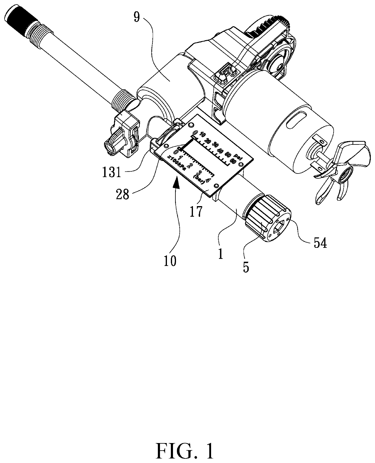
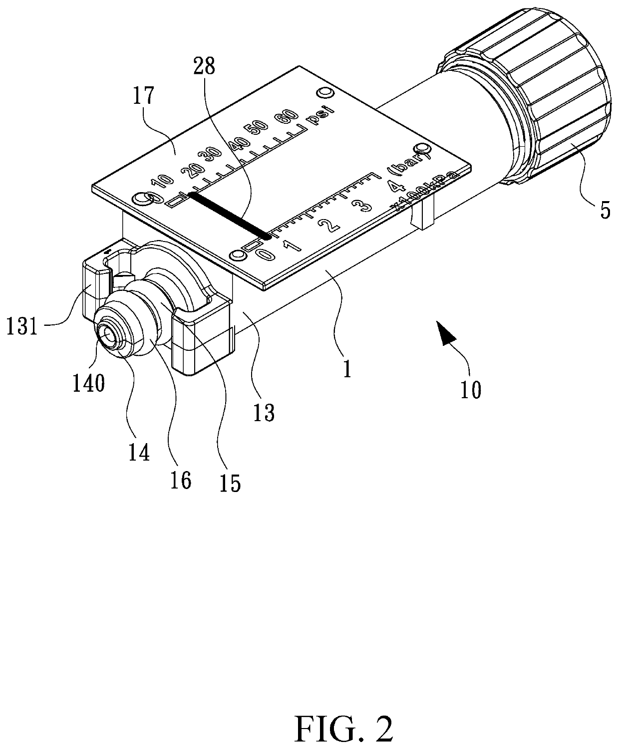
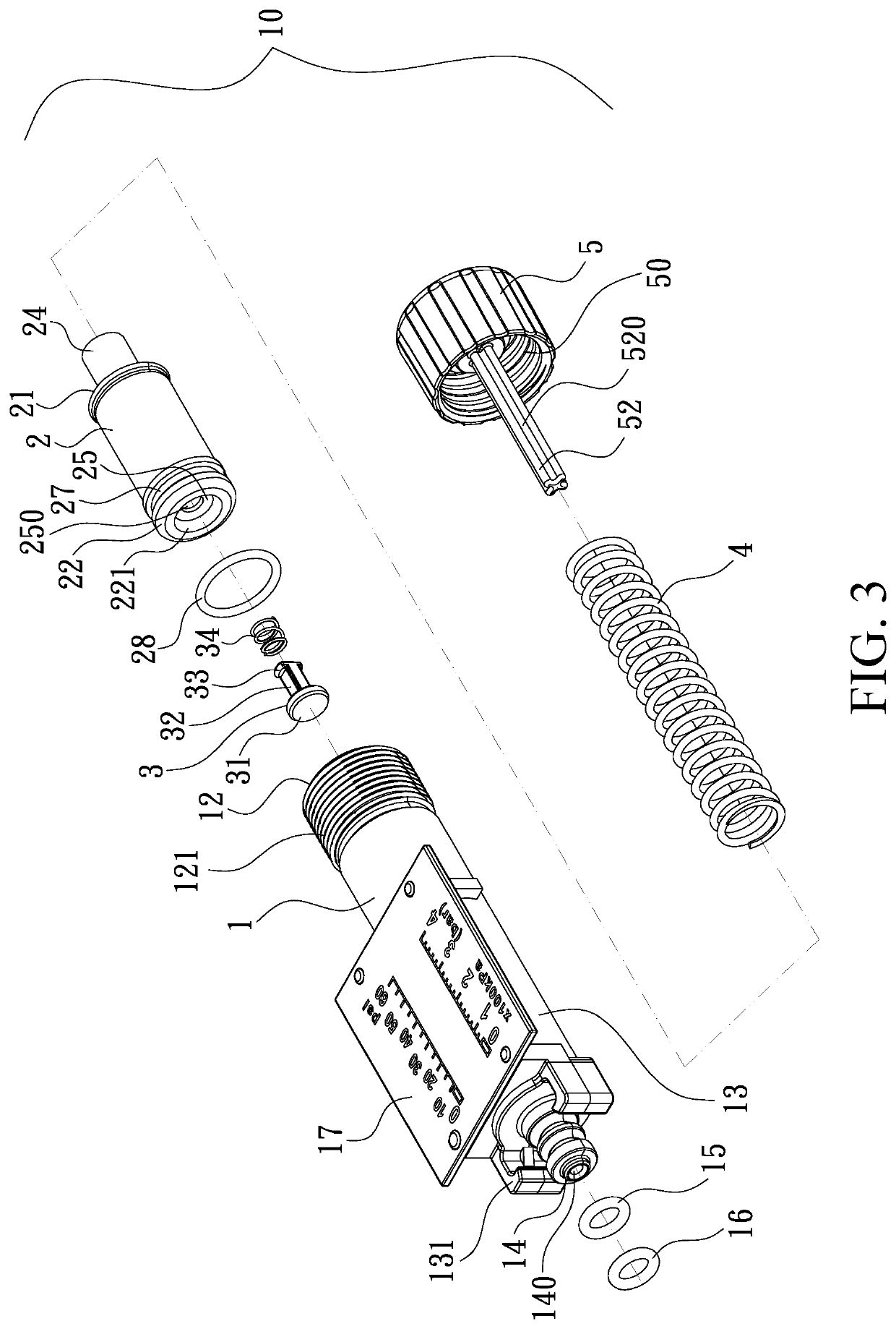
[0022]With reference to FIGS. 1-4, a pressure gauge 10 according to a preferred embodiment of the present invention is connected with an air compressor 9, and the pressure gauge 10 comprises a hollow tube 1 which is transparent and is formed in a cylinder shape, and the hollow tube 1 includes an accommodation chamber 11, a first open segment 12 formed on a first end of the hollow tube 1 and having male threads 121, a first distal segment 13 formed on a second end of the hollow tube 1 and having two retainers 131 formed on the first distal segment 13, a connector 14 fixed on a center of an outer side of the first distal segment 13 and having a conduit 140 which communicates with the accommodation chamber 11 of the hollow tube 1, two airtight O-rings 15, 16 separately arranged on the connector 15, and a display unit 17 mounted on an outer wall of the hollow tube 1 adjacent to the first distal segment 13 and having at least one scale graduation to indicate a pressure value of the air comp


PUM


Abstract

An air compressor having a pressure gauge, the pressure gauge contains: a hollow tube, a drive element, an anti-leak spring, a resilient element, and a cap. The hollow tube includes an accommodation chamber, a connector having a conduit, and a display unit. The drive element includes a protection unit, a first open segment, a second distal segment, a receiving portion, a hollow extension, and a protrusion. An anti-leak spring is received in the hollow extension of the drive element and abuts against the protrusion and the protection unit. The resilient element is received in the receiving portion. The cap includes a seat, a push bolt, and multiple passages. The accommodation chamber has a first fixing section and a second fixing section, a diameter of which is different from that of the first fixing section. The hollow tube further includes a tilted surround section and at least one discharge orifice.

Description


Claims


Application Information

Patent Timeline
Owner UNIK WORLD IND CO LTD
Why Eureka
Try Eureka