Bogie Frame With Asymmetrical Support Beam and Bogie of a Rail Vehicle

a technology of asymmetric support beam and bogie, which is applied in the direction of bogies, railway components, wheel axle self-adjustments, etc., to achieve the effect of reducing the stiffness of the bogie fram

Pending Publication Date: 2021-07-01
BOMBARDIER TRANSPORTATION GMBH
View PDF3 Cites 0 Cited by
  • Summary
  • Abstract
  • Description
  • Claims
  • Application Information

AI Technical Summary

Benefits of technology

This patent describes a new type of vehicle's wheelset system with a specialized framework called the bogie frame. Unlike traditional vehicles where all components are connected together, this bogie frame can be flexed or bent without losing its strength. It also has a strong supporting part that supports the entire weight of the car. By allowing the wheels to move around independently, these frames provide better stability during operation.

Problems solved by technology

The technical problem addressed by this patent is how to combine both a good roll performance and a good compensating for track unevenness without requiring complicated and expensive components.

Method used


Image

  • Bogie Frame With Asymmetrical Support Beam and Bogie of a Rail Vehicle
  • Bogie Frame With Asymmetrical Support Beam and Bogie of a Rail Vehicle
  • Bogie Frame With Asymmetrical Support Beam and Bogie of a Rail Vehicle

Examples


Embodiment Construction

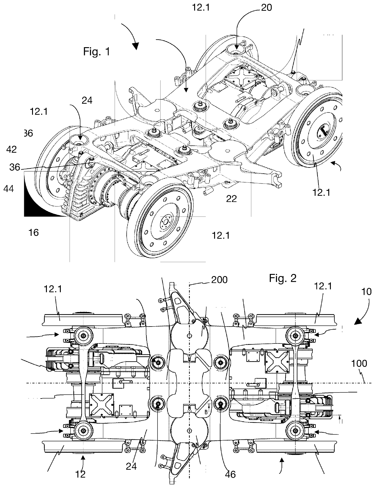
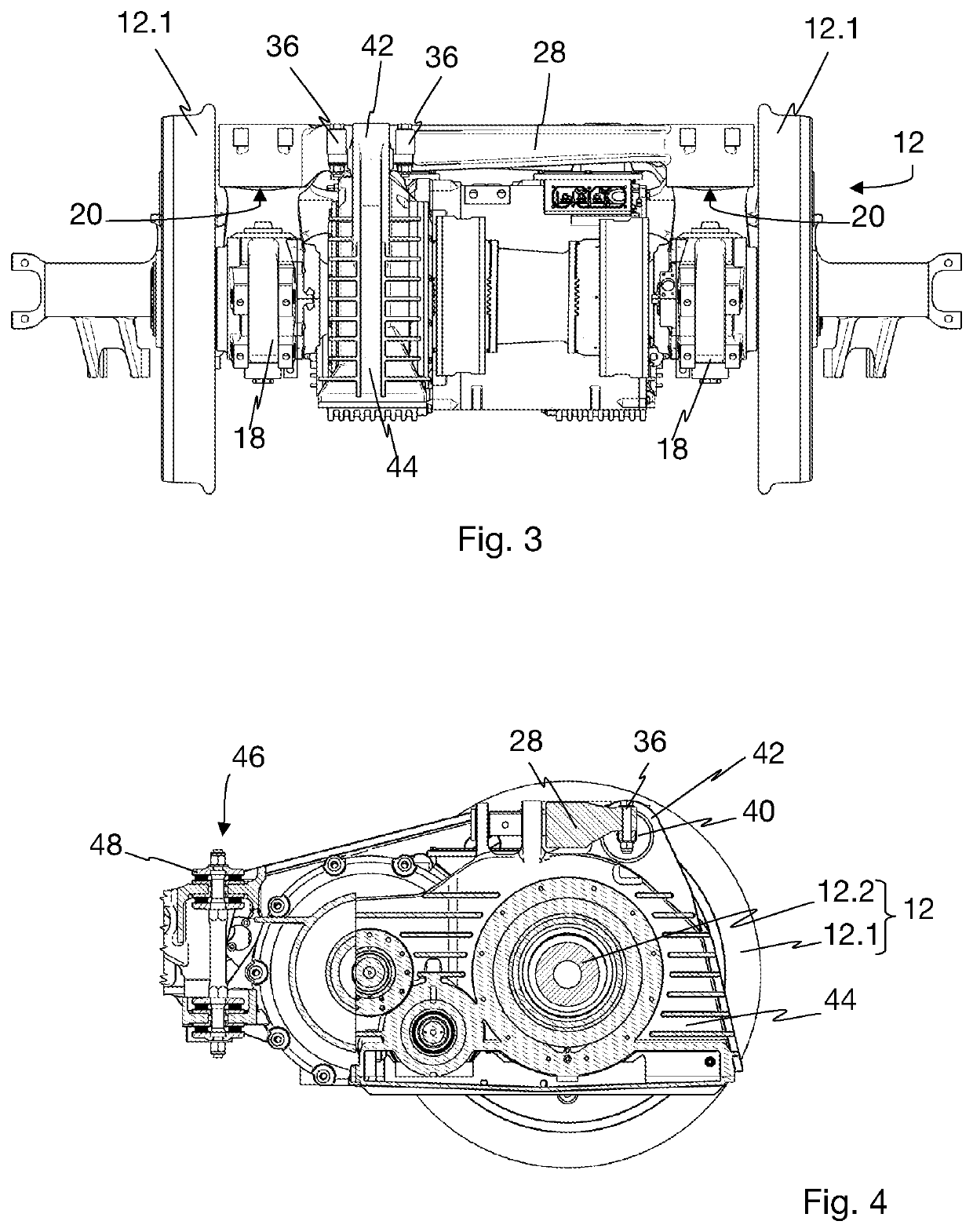
[0047]With reference to FIGS. 1 to 4, a bogie 10 for a rail vehicle comprises two sets of left and right wheels 12, a unitary bogie frame 14 supported on the two sets of wheels 12 and two drive units 16 attached to the bogie frame 14, each for driving one of the sets of wheels.

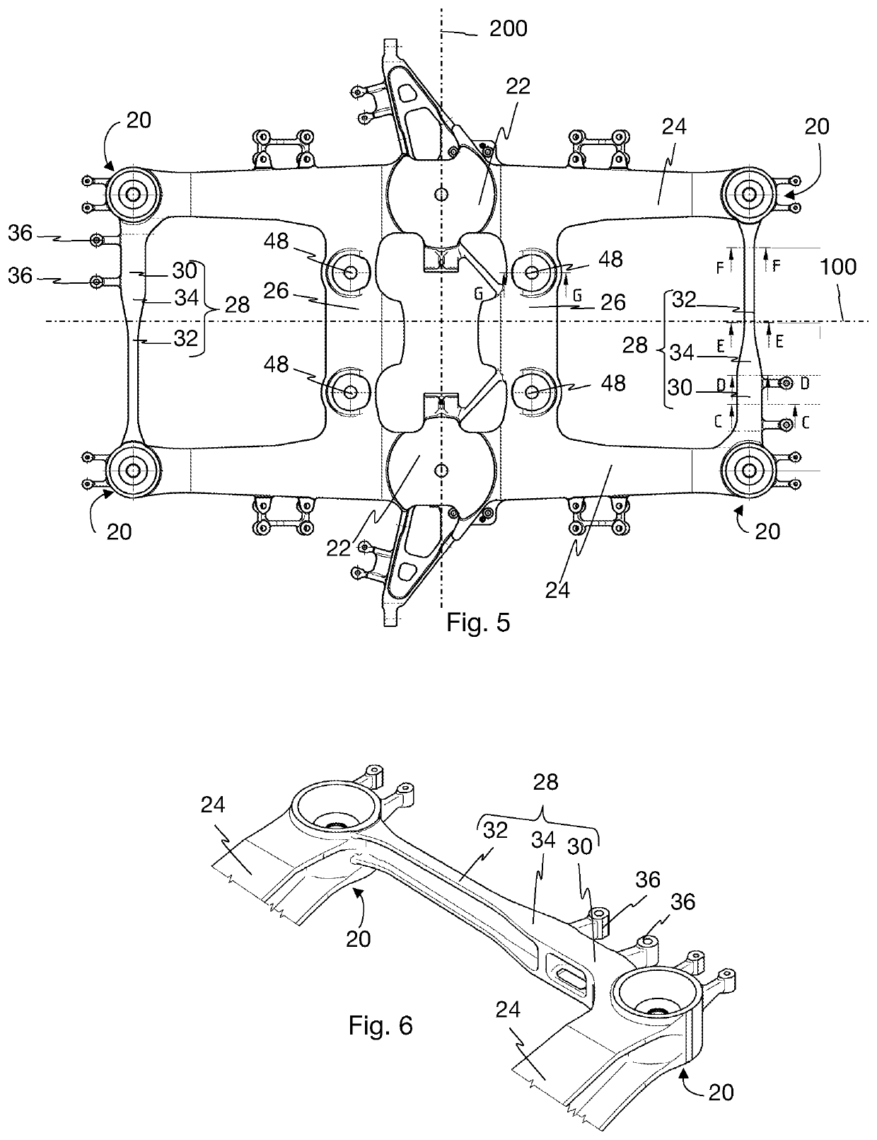
[0048]Each set of wheels 12 consists of two wheels 12.1 mounted on a common axle 12.2. Two parallel wheel bearings 18 are located between the wheels 12.1 for guiding a rotation movement of each of the wheels 12.1 about a spin axis 100 of the axle 12.2. The bogie frame 14 comprises primary suspension interfaces 20 for mounting primary suspension elements (not shown) between the wheel bearings 18 and the bogie frame 14. The bogie frame further comprises two secondary suspensions seats 22, each for accommodating a vertical spring (not shown) of a secondary suspension, located at symmetric locations each on a respective side of a median longitudinal plane 100 of the bogie frame 14, each closer to a median transverse


PUM


Abstract

A unitary bogie frame for a bogie of a rail vehicle, includes: two side beams and at least one support beam extending in the transverse direction of the bogie frame and rigidly connected to each of the two side beams. The support beam includes a support portion for supporting a drive unit of the bogie and a slender portion. The support portion is directly connected to one of the two side beams and is connected to the other of the two side beams through the slender portion. The planar second moment of area and the polar second moment of area of any cross section of the support portion of the support beam are at least twice as great as the planar second moment of area and the polar second moment of area, respectively, of any cross-section of the slender portion of the support beam.

Description


Claims


Application Information

Patent Timeline
Owner BOMBARDIER TRANSPORTATION GMBH
Why Eureka
Try Eureka