Compressor system

a compressor system and compressor technology, applied in the direction of machines/engines, couplings, liquid fuel engines, etc., can solve the problems of hindering an increase in adversely affecting etc., to improve the rotor dynamics increase the rotation speed of the rotary sha

Active Publication Date: 2021-07-08
MITSUBISHI HEAVY INDUSTIES COMPRESSOR CORP
View PDF5 Cites 0 Cited by
  • Summary
  • Abstract
  • Description
  • Claims
  • Application Information

AI Technical Summary

Benefits of technology

The invention improves the stability and efficiency of an air conditioning (AC) compressor by reducing vibrations caused by the rotating parts. This results in better performance and longer lifespan for AC systems.

Problems solved by technology

This patent describes a problem with traditional centrifuge compressors where two rotating parts - one for driving the compression process and another for creating power. These components have different sizes and shapes, which makes it difficult to connect them together effectively without causing issues such as vibrations or leaks in the system.

Method used


Image

  • Compressor system
  • Compressor system
  • Compressor system

Examples


Embodiment Construction

[0011]Hereinafter, an embodiment for carrying out the compressor system according to the present disclosure will be described with reference to the attached drawings. However, the present disclosure is not limited to this embodiment only.

[0012](Compressor System)

[0013]Hereinafter, the compressor system according to the present embodiment will be described with reference to FIGS. 1 to 3.

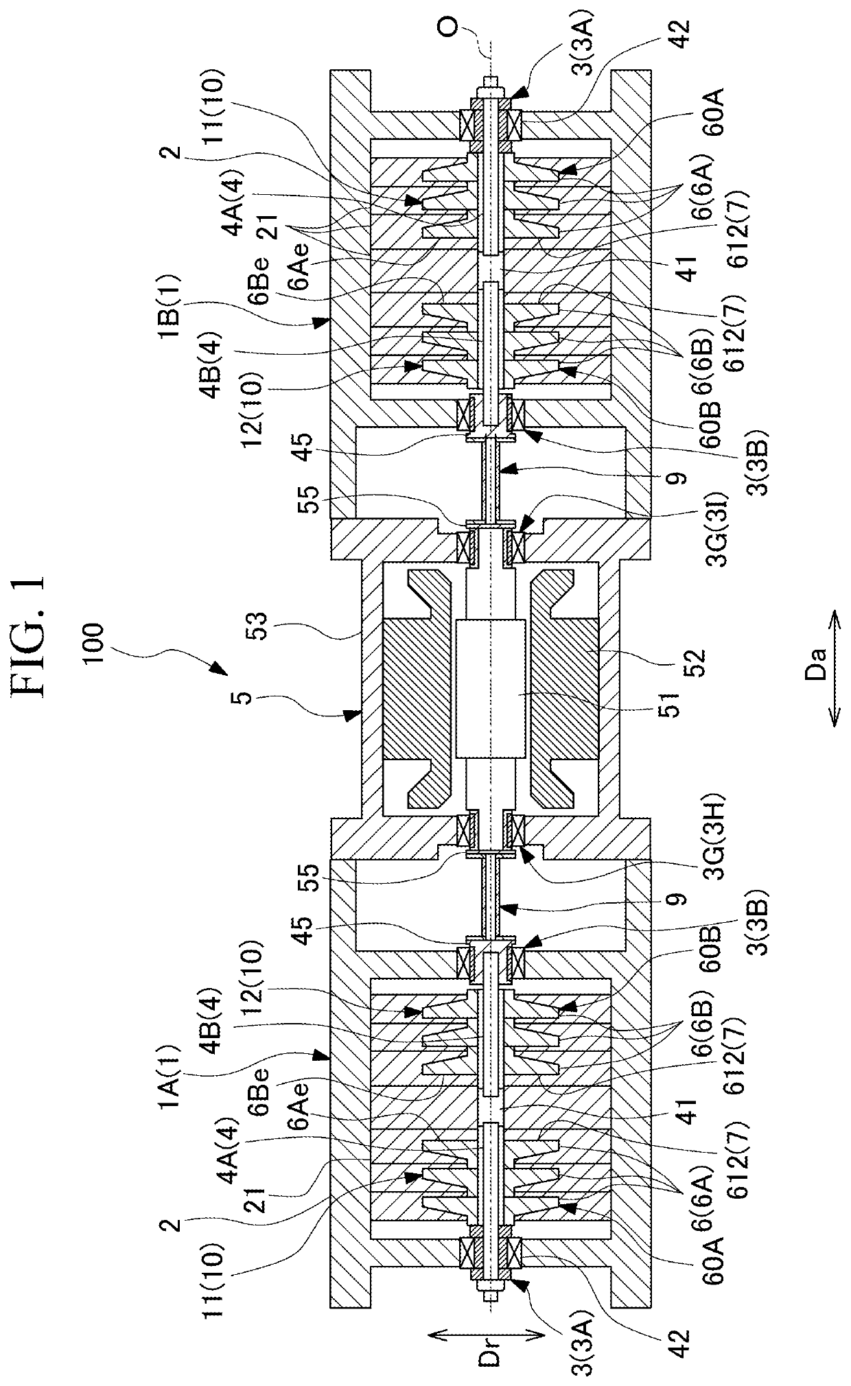
[0014]As illustrated in FIG. 1, the compressor system 100 includes a compressor 1, a motor 5, and a coupling shaft 9. In the present embodiment, the compressor 1 is disposed on both sides of the motor 5 with the motor 5 interposed therebetween. The compressor 1 includes a low-pressure side first compressor 1A disposed on a first side (left side with respect to the motor 5 in FIG. 1) in an axial direction Da described below with the motor 5 interposed between, and a high-pressure side second compressor 1B disposed on a second side (right side with respect to the motor 5 in FIG. 2) in the axial direction D


PUM


Abstract

A compressor system includes a compressor including a rotary shaft, an impeller, and a casing, a motor including a motor rotor disposed coaxially with the rotary shaft, and a coupling shaft coupling the motor rotor to the rotary shaft. The compressor includes a compressor bearing that rotatably supports the rotary shaft, and a compressor connecting hub that is fixed to the rotary shaft at a position where the compressor connecting hub overlaps the compressor bearing in the axial direction and at a position on an inner side in the radial direction. The coupling shaft is allowed to alleviate misalignment with the compressor connecting hub. The compressor bearing rotatably supports an outer peripheral surface of the compressor connecting hub.

Description


Claims


Application Information

Patent Timeline
Owner MITSUBISHI HEAVY INDUSTIES COMPRESSOR CORP
Why Eureka
Try Eureka