Elliptical trainer

a technology of elliptical trainer and pedal, which is applied in the field of elliptical trainer, can solve the problems of poor durability, poor operation, and the majority of conventional elliptical trainers cannot adjust the stride of the pedal,

Active Publication Date: 2021-08-12
DYACO INT INC
View PDF0 Cites 0 Cited by
  • Summary
  • Abstract
  • Description
  • Claims
  • Application Information

AI Technical Summary

Benefits of technology

This invention relates to an exercise machine that has several technical features: it includes various components like resistors, paddles for strength training or rehabilitation purposes; there also have multiple different types of movements such as backward movement, forward motion, up/down motions, etc.; all these allow users to perform their workouts more efficiently by providing them with greater muscle power during certain activities.

Problems solved by technology

There have been technical problem addressed in this patented technology: how to provide an exercise apparatus where steps between different levels may vary based upon their height without causing any issues such as wear caused by friction while maintaining good usability over time due to increased maintenance costs associated therewith.

Method used


Image

  • Elliptical trainer
  • Elliptical trainer
  • Elliptical trainer

Examples


Embodiment Construction

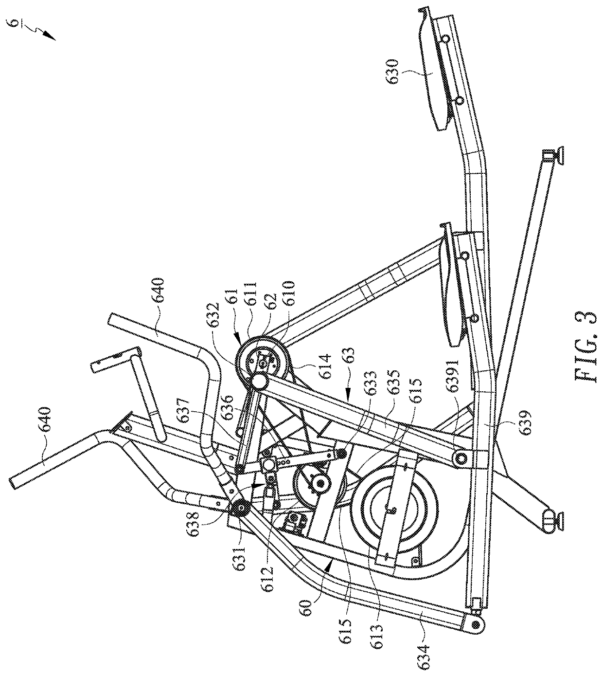
[0023]FIG. 3 is a side view of an elliptical trainer 6 in accordance with an embodiment of the present invention. FIG. 4 is a partially enlarged view of the elliptical trainer 6 shown in FIG. 3. Referring to FIGS. 3 and 4, the elliptical trainer 6 includes a supporting frame 60, a resistance device 61, two cranks 62, and two operation units 63. The resistance device 61 includes a shaft 610. The two cranks 62 are respectively arranged at the left and right side of the shaft 610, and a first end of each crank 62 is connected to the shaft 610. The two operation units 63 are respectively arranged at left and right side of the shaft 610 and each connects to one crank 62. Each operation unit 63 includes a pedal 630, a first pivot 631, a second pivot 632, a third pivot 633, a front swing rod 634, a rear swing rod 635, a middle swing rod 636, a push rod 637, an amplitude-linking mechanism 638, and a pedal-supporting rod 639. The first pivot 631 is mounted on the supporting frame 60. The second


PUM


Abstract

An embodiment of the present invention provides an elliptical trainer composed of structures featuring a first amplitude, a second amplitude, and a third amplitude. By the driving of cranks and the combination of the three amplitudes, the elliptical trainer's pedals move along a closed ellipse path. In addition, the first amplitude is more than twice or three times of the third amplitude, resulting in a wide adjustment range of the stride of the pedal. Accordingly, the elliptical trainer is applicable to users with various heights.

Description


Claims


Application Information

Patent Timeline
Owner DYACO INT INC
Why Eureka
Try Eureka