LED filament and LED light bulb

Pending Publication Date: 2022-02-10
ZHEJIANG SUPER LIGHTING ELECTRIC APPLIANCE
View PDF7 Cites 0 Cited by
  • Summary
  • Abstract
  • Description
  • Claims
  • Application Information

AI Technical Summary

Benefits of technology

[0011]It is noted that the present disclosure includes one or more inventive solutions currently claimed or not claimed, and in order to avoid confusion between the illustration of these embodiments in the specification, a number of possible inventive aspects herein may be collectively referred to “present/the invention.”

Problems solved by technology

However, incandescent bulbs are generally with lower efficiency in terms of energy application, and about 90% of energy input can be converted into a heat form to dissipate.
In addition, because the incandescent bulb has a very limited lifespan (about 1,000 hours), it needs to be frequently replaced.
At present, LED light bulbs using LED filaments as illumination sources still have the following problems to be improved.
The illumination appearance of the single LED hard filament cannot meet the general needs in the market.
In contrast, the LED hard filament is difficult to achieve such uniform illumination appearances.
There are many reasons why LED hard filaments are difficult to achieve the uniform illumination appearance.
In addition to the aforementioned lower bendable property, one of the reasons is that the substrate blocks the light emitted by the LED chip, and furthermore the light generated by the LED chip is displayed similar to a point light source which causes the light showing concentrated illumination and with poor illumination uniformity.
On the other hand, the light ray distribution similar to a point light source may result in uneven and concentrated illumination.
However, by utilizing the LED soft filament made of the FPC, the FPC has a thermal expansion coefficient different from that of the silicon gel coated covering the LED soft filament, and the long-term use causes the displacement or even degumming of the LED chips.
Moreover, the FPC may not beneficial to flexible adjustment of the process conditions and the like.
Besides, during bending the LED soft filament it has a challenge in the stability of the metal wire bonded between LED chips.
When the arrangement of the LED chips in the LED soft filament is dense, if the adjacent LED chips are connected by means of metal wire bonding, it is easy to cause the stress to be concentrated on a specific part of the LED soft filament when the LED soft filament is bent, thereby the metal wire bonding between the LED chips are damaged and even broken.
Since the LED chips are arranged in the LED filaments, and the LED chips are relatively hard objects, it is difficult for the LED filaments to be bent into a desired shape.
Moreover, the LED filament is also prone to cracks due to stress concentration during bending.
However, since the plurality of LED filaments need to be installed in a single LED light bulb, and these LED filaments need to be fixed individually, the assembly process will be more complicated and the production cost will be increased.
In addition, since the driving requirements for lighting the LED filament are substantially different from for lighting the conventional tungsten filament lamp.
According to the aforementioned patents, which respectively use a PCB board, adjust the chips arrangement or form a heat dissipation layer, the heat dissipation of the filament of the lamp can be improved to a certain extent correspondingly; however, the heat is easy to accumulate due to the low efficiency in heat dissipation.
However, due to the fact that the substrate is formed by silicon resin, the defect of poor heat resistance is a disadvantage.

Method used


Image

  • LED filament and LED light bulb
  • LED filament and LED light bulb
  • LED filament and LED light bulb

Examples


Example

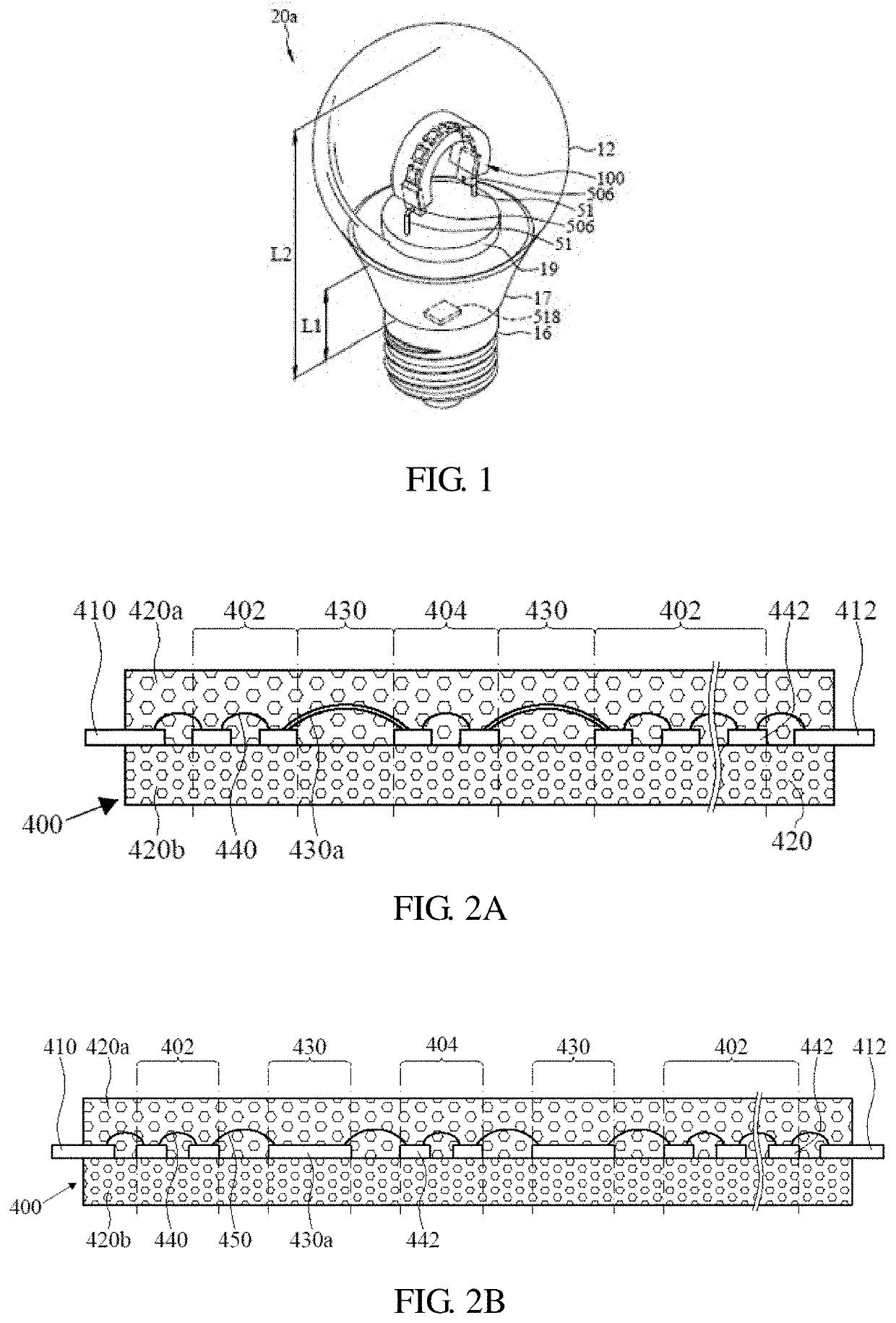
[0045]The present disclosure provides a novel LED filament and its application the LED light bulb. The present disclosure will now be described in the following embodiments with reference to the drawings. The following descriptions of various implementations are presented herein for purpose of illustration and giving examples only. This invention is not intended to be exhaustive or to be limited to the precise form disclosed. These example embodiments are just that—examples—and many implementations and variations are possible that do not require the details provided herein. It should also be emphasized that the disclosure provides details of alternative examples, but such listing of alternatives is not exhaustive. Furthermore, any consistency of detail between various examples should not be interpreted as requiring such detail—it is impracticable to list every possible variation for every feature described herein. The language of the claims should be referenced in determining the requi


PUM

PropertyMeasurementUnit
Poweraaaaaaaaaa
Poweraaaaaaaaaa
Electric chargeaaaaaaaaaa

Abstract

An LED filament comprising a plurality of LED filament units, each of the plurality of LED filament units includes a LED chip with an upper surface and a lower surface opposite to the upper surface of the LED chip, and a light conversion layer comprising a top layer and a base layer, and the base layer comprises an upper surface and a lower surface opposite to the upper surface of the base layer, where the top layer with an upper surface and a lower surface opposite to the upper surface of the top layer is disposed on at least two sides of each of the LED chips, the lower surface of each of the LED chips is close to the upper surface of the base layer, and the upper surface of the top layer is away from each of the LED chips.

Description


Claims


Application Information

Patent Timeline
Owner ZHEJIANG SUPER LIGHTING ELECTRIC APPLIANCE
Why Eureka
Try Eureka