Apparatus and method for downhole fluid separation
a technology of fluid separation and apparatus, applied in the field of apparatus and method for fluid separation in the well, can solve the problems of limited operation window for oil production flow rate and watercut, insufficient separation degree, complexity and high installation cost, etc., and achieve the effect of enhancing the efficiency of the underground separation chamber
- Summary
- Abstract
- Description
- Claims
- Application Information
AI Technical Summary
Benefits of technology
Problems solved by technology
Method used
Image

Examples
first embodiment
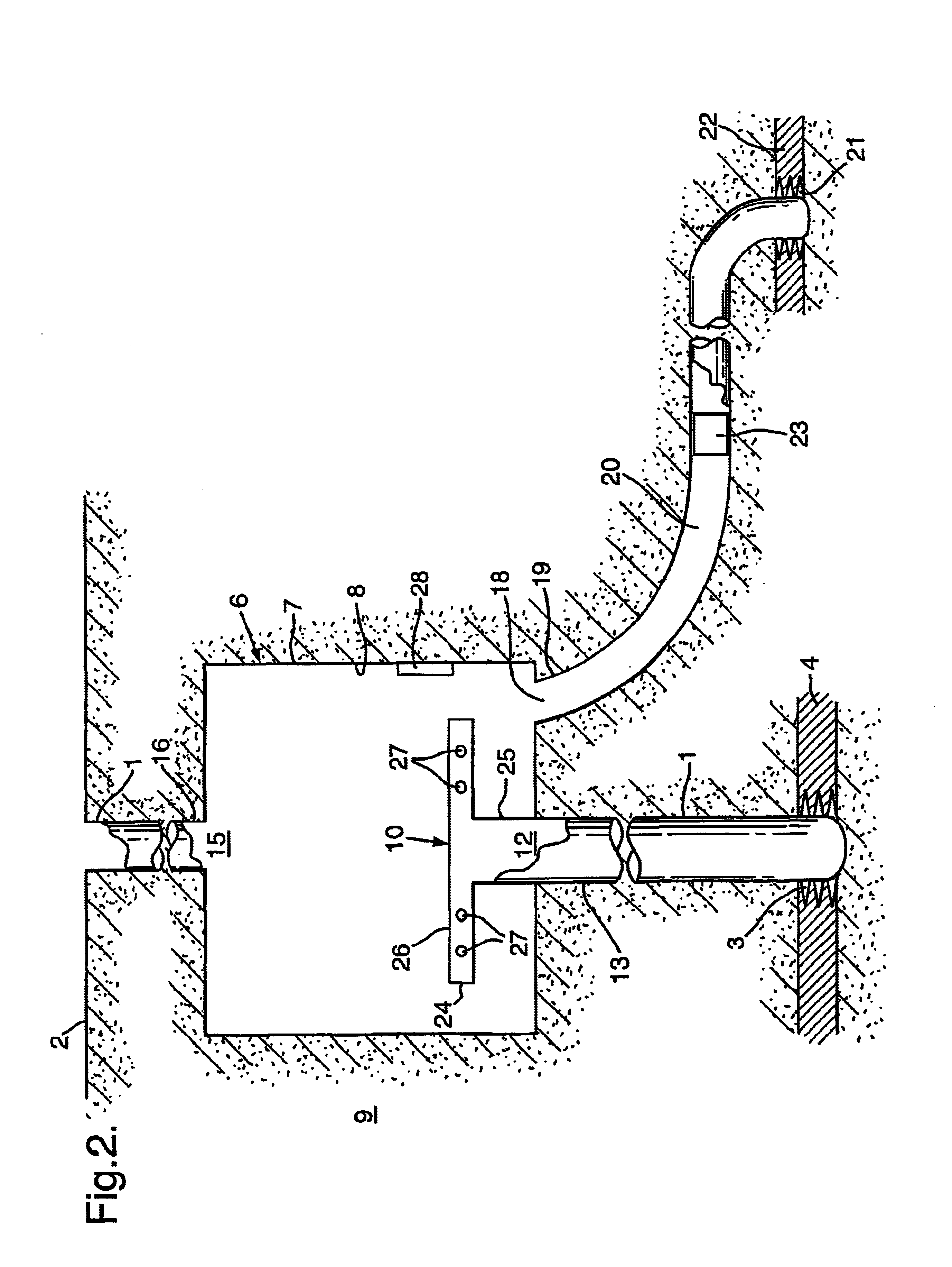
Reference is now made to FIG. 2, which shows schematically the present invention. The well 1, extending from the surface 2 to the underground production formation 4, is provided with a separation chamber 6 that is arranged in an underreamed section 7 of the well 1. The separation chamber 6 has a substantially circular cross section. The vertical-wall 8 of the separation chamber 6 is formed by the surrounding formation 9, but it will be understood that the wall can also be provided with a well tubular, such as a casing. The wall of the separation chamber also forms the wall of the separator.
In the separation chamber 6 there is arranged an oil / water separator 10 comprising an inlet 12 to receive well fluid from the inlet well section 13 below the separation chamber 6. The separator 10 further comprises an outlet 15 for an oil-enriched component opening into the well section 16 above the separation chamber 6 and an outlet 18 opening into a discharge well section 19 below the-separation
second embodiment
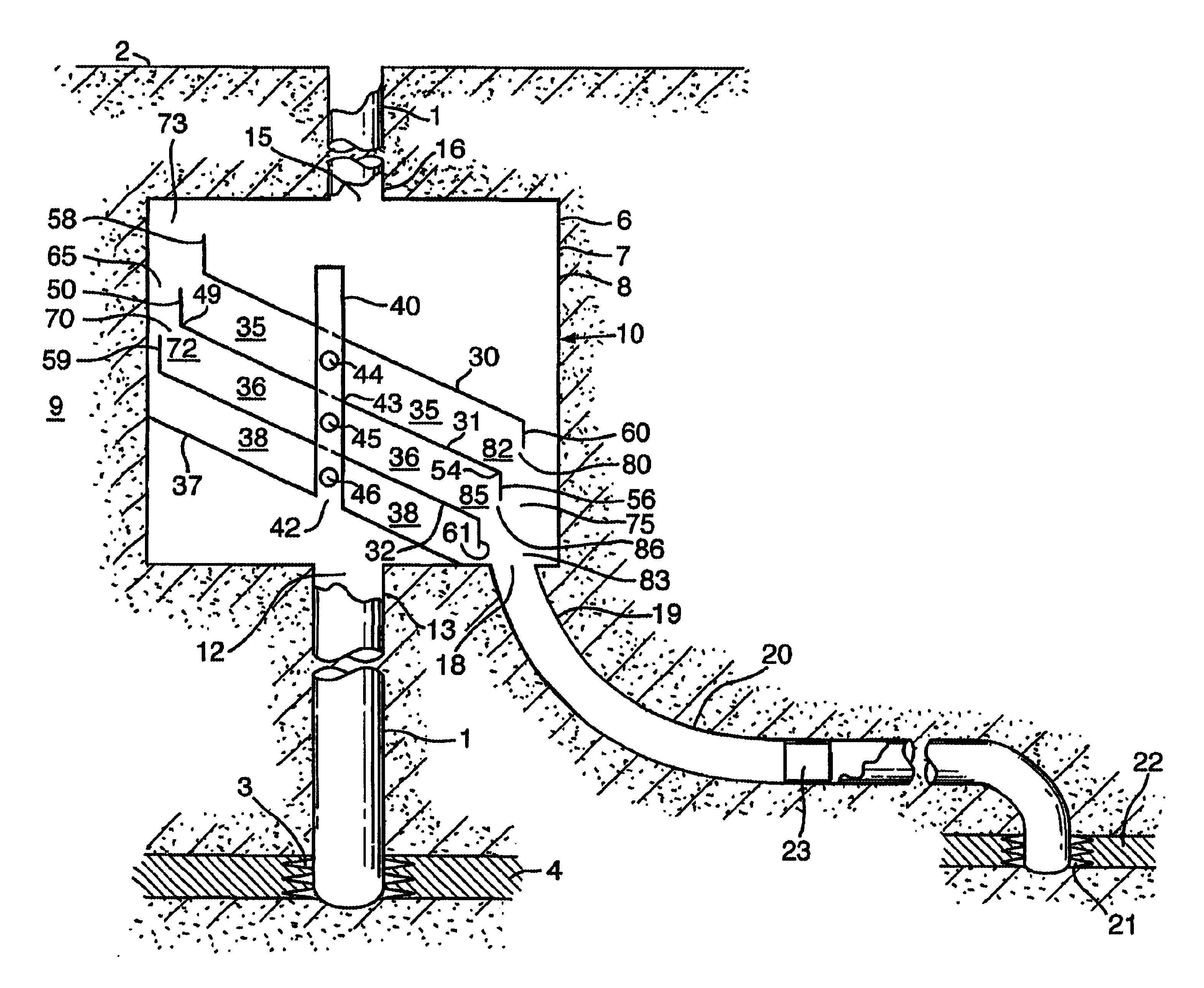
Reference is now made to FIGS. 3 and 4, which show the present invention. In this embodiment, the static separator 10 further comprises a stack of inclined, substantially flat plates 30, 31, 32 that are arranged substantially parallel to each other and vertically spaced apart at an equal distance. The space delimited between two neighbouring plates is referred to as the separation space. For example, plates 30 and 31 define the separation space 35, plates 31 and 32 define the separation space 36. Underneath the lowest plate 32 of the stack of plates a parallel base plate 37 is arranged, wherein the outer rim of the base plate sealingly engages the walls of the separation chamber 6. Between the plate 32 and the base plate 37 a further separation space 38 is defined.
The stack of plates is traversed by the inlet conduit 40, which extends vertically upwardly from an opening 42 through the stack of plates in the centre of the separation chamber 6. The passage of the inlet conduit through a
PUM
| Property | Measurement | Unit |
|---|---|---|
| Speed | aaaaa | aaaaa |
| Thickness | aaaaa | aaaaa |
| Flow rate | aaaaa | aaaaa |
Abstract
Description
Claims
Application Information
 - R&D Engineer
- R&D Manager
- IP Professional
- Industry Leading Data Capabilities
- Powerful AI technology
- Patent DNA Extraction
Browse by: Latest US Patents, China's latest patents, Technical Efficacy Thesaurus, Application Domain, Technology Topic.
© 2024 PatSnap. All rights reserved.Legal|Privacy policy|Modern Slavery Act Transparency Statement|Sitemap