Control of ink jet nozzle prefiring

Inactive Publication Date: 2005-03-08
CANON KK
View PDF28 Cites 31 Cited by
  • Summary
  • Abstract
  • Description
  • Claims
  • Application Information

AI Technical Summary

Benefits of technology

In yet another aspect, the invention is a method in an ink jet printing apparatus which performs printing by using a print head. The method includes the steps of prefiring the print head to eject ink for maintaining printing quality after a first time interval during a printing operation, driving the print head based on data to be printed, and driving the print head based on the first time interval during the printing operation so as to enhance a power of ejecting

Problems solved by technology

Residual ink in the unused nozzles tends to dry or coagulate, clogging the nozzles.
Then, when then ink jet printer attempts to use the clogged nozzles, the nozzles might not eject ink properly, resulting in poor image quality.
Moving the print head or print heads to the home position and ejecting ink from the nozzles takes considerable time.
As a result, performing the prefire operation at a short time interval unacceptabl

Method used


Image

  • Control of ink jet nozzle prefiring
  • Control of ink jet nozzle prefiring
  • Control of ink jet nozzle prefiring

Examples


Embodiment Construction

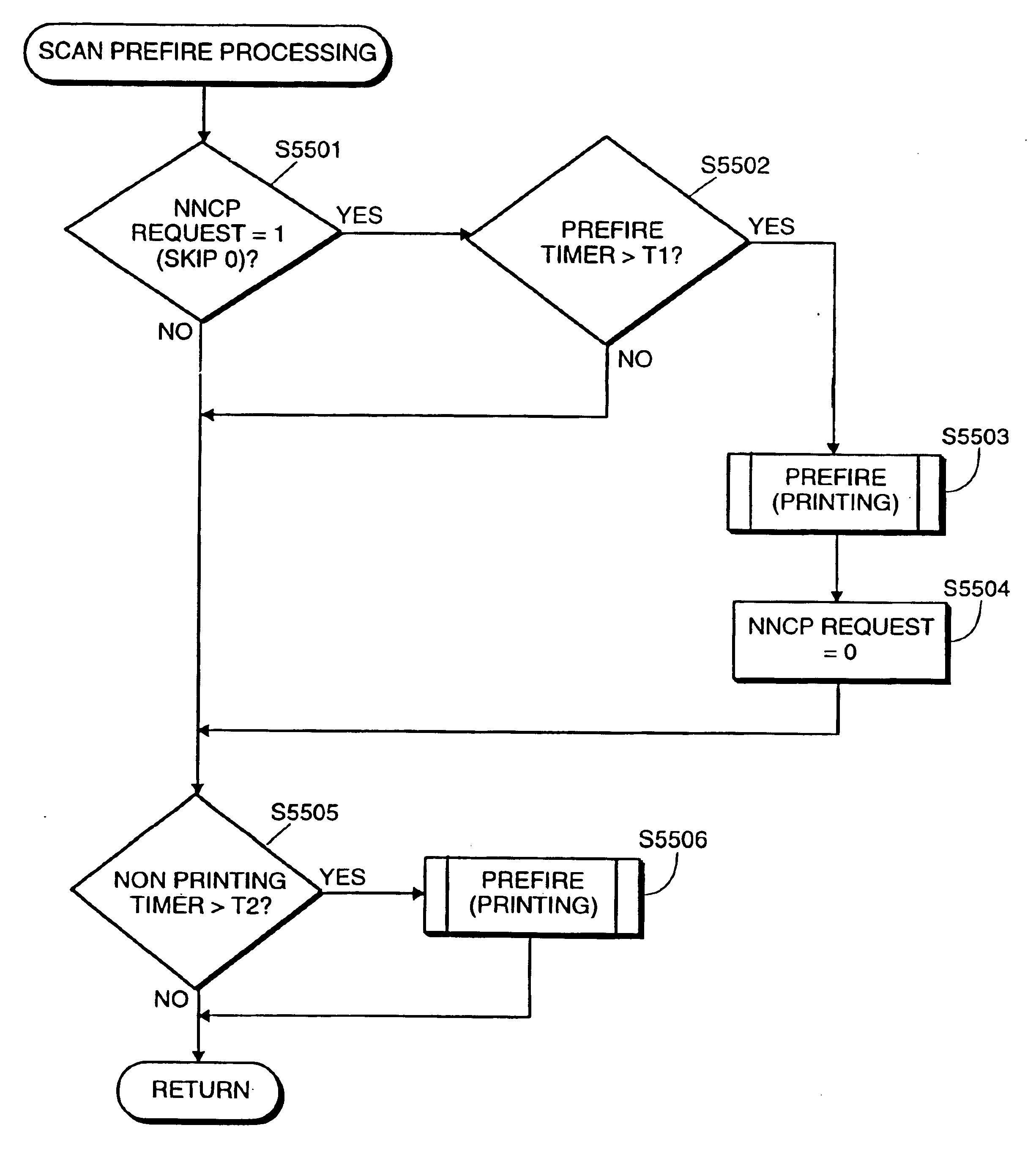
This detailed description of the preferred embodiment is organized into sections, as follows:1.0 Mechanical1.1 Structure1.2 Cleaning1.3 Ink Cartridge1.4 Print Head Structure1.5 Print Modes2.0 Electrical2.1 System Architecture2.2 System Function2.3 Control Logic2.4 General Operation3.0 Architecture of Printer Software3.1 Operating System3.2 Initialization3.3 Tasks3.4 Interrupt Handlers3.5 Cyclic Handlers3.6 Commands To And From The Host Processor3.6.1 Control Commands3.6.2 Setting Commands3.6.3 Maintenance Commands4.0 Automatic Sheet Feed Control4.1 ASF, Line Feed and Eject Speed Selection4.2 Early Determination of Paper Load Success4.3 Print Head Maintenance During Paper Load5.0 Carriage Control5.1 Margin And Direction Control5.1.1 Printer Driver Initiated Operation5.1.2 Print Control Operation5.2 Automatic Ink Ejection and Satelliting Control6.0 Printer Control Based On Head Alignment7.0 Dual Head Multicolor Printing8.0 Prefiring and Pulse Width Modulation8.1 Prefire Control8.1.1 Pref


PUM


Abstract

An ink jet printing apparatus which performs printing by using a print head. The print head has at least a predetermined number of nozzles to eject ink. The apparatus includes a first prefiring mechanism for causing the print head to perform a prefiring operation to eject ink from nozzles of the print head for maintaining printing quality after a first time interval during a printing operation. The apparatus also includes a driving mechanism for driving nozzles of the print head based on data to be printed, and a second prefiring mechanism for causing the print head to perform the prefiring operation in a case where a number of the nozzles to be driven is changed. Preferably, the apparatus further includes a shifting mechanism for causing the driving mechanism to drive the nozzles of the print head based on the first time interval during the printing operation so as to enhance a power of ejecting ink and continue the printing operation after the first time interval without performing the prefiring operation. The shifting mechanism also preferably delays the prefiring operation to a second time interval longer than the first time interval, and after the second time interval, the first prefiring mechanism causes the print head to perform the prefiring operation. In a case where the number of nozzles to be driven is changed within a time duration after the first time interval and during the second time interval, the second prefiring mechanism causes the print head to perform the prefiring operation.

Description


Claims


Application Information

Patent Timeline
Owner CANON KK
Why Eureka
Try Eureka