Connector for connecting with flexible substrates

Inactive Publication Date: 2005-05-17
SMK CORP
View PDF4 Cites 3 Cited by
  • Summary
  • Abstract
  • Description
  • Claims
  • Application Information

AI Technical Summary

Benefits of technology

[0028]The metal guides which are fixed to the housing reinforce the pivot-supporting holes. Therefore, the pivot-supporting holes can withstand rough treatment from continuous operation or excessive force.
[0029]The operation lever is turned when the flexible substrate is extracted from the connector so that the slider can move to the backward position. The press plate on the slider releases the pressure on the flexible substrate so that the contact points of the contacts are no longer in contact with the flexible substrate in the insertion opening. Therefore, the releasing operation can be completed by extracting the flexible substrate which can be inserted into or extracted from the insertion opening freely.
[0030]The present invention provides a connector for securely and electrically connecting flexible substrates with advantages over the prior art. The present connector applies zero insertion force (ZIF) on the flexible substrate during insertion into the connector and provides a uniform elastic contact pressure between the flexible substrate and a set of electrical contacts. The flexible substrate can be easily manipulated to electrically engage with a set of electrical contacts. The locking mechanism is reliable, can be easily manipulated, prevents the unintentional release of the flexible substrate, and prevents damage to the flexible substrate during insertion and retention. The connector device resists breakage at pivot points and is durable under continued operation and abuse. The unitary release of elastic contact pressure on the flexible substrate prevents damage to the flexible substrate and the set of contacts. Furthermore, the connector device allows easy insertion and extraction of a flexible substrate by operation of single releasable locking lever.

Problems solved by technology

However, the area surrounding the pivot-supporting holes 113 is too weak for a small connector 101.
Furthermore, vibration may cause the operation lever 104 to release the flexible substrate 120 from the contacts 105, 106, thereby risking a loss of electrical contact since the operation lever 104 is not secured at the position where it is parallel to the housing 102.

Method used


Image

  • Connector for connecting with flexible substrates
  • Connector for connecting with flexible substrates
  • Connector for connecting with flexible substrates

Examples


Example

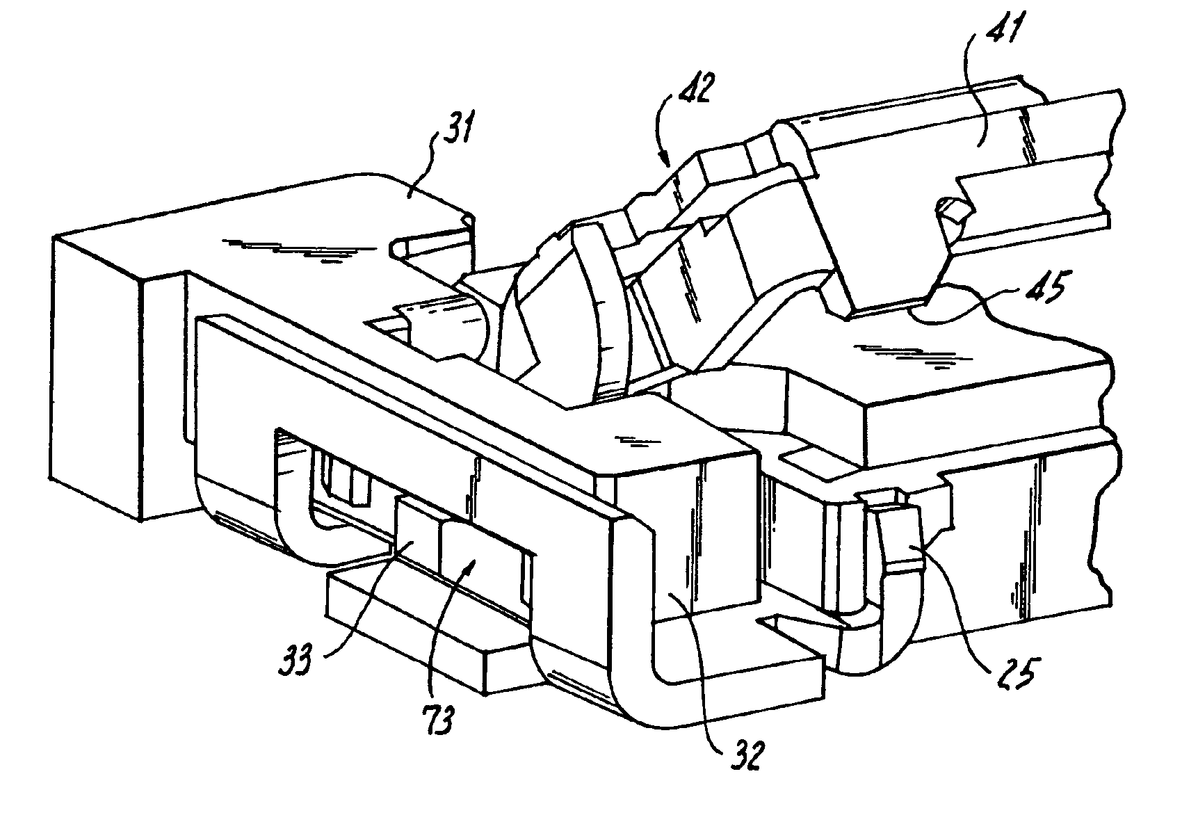
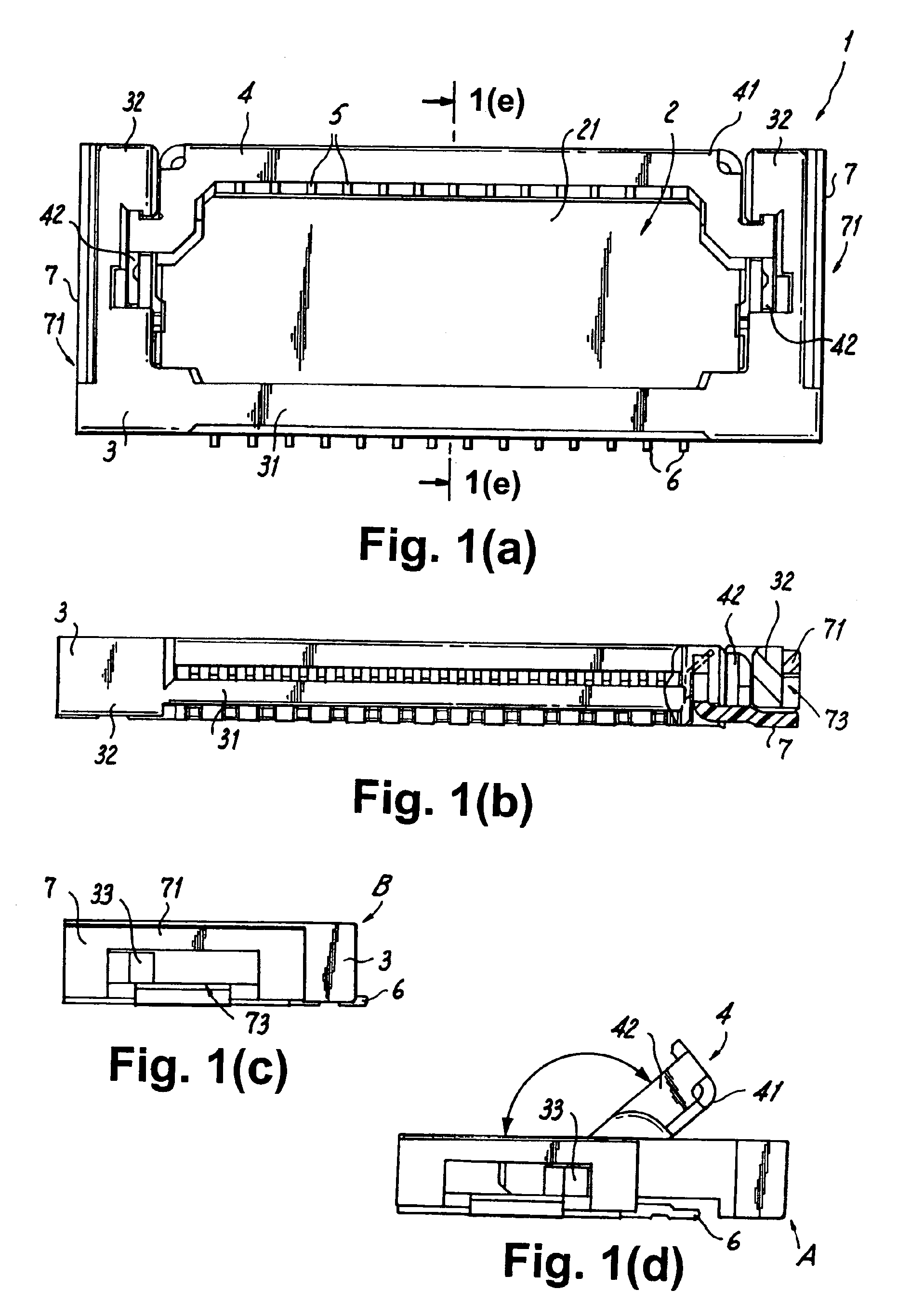
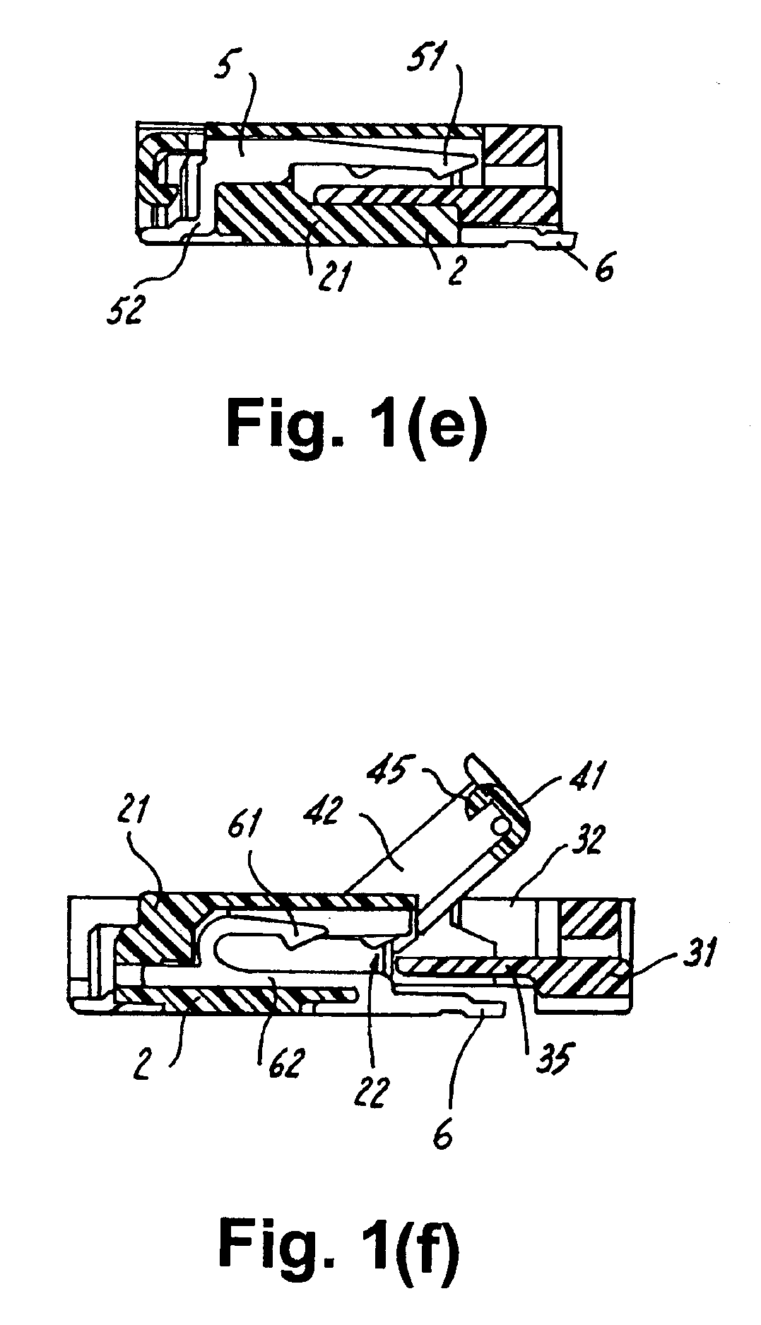
[0067]A flexible substrate connector 1 includes a housing 2, a slider 3, an operation lever 4, and multiple contacts 5, 6, as shown in FIGS. 1(a)-(f), and FIGS. 2(a) and (b). The contacts 5, 6 include contact points 51, 61, respectively. The connector 1 establishes an electrical connection between an element such as a printed circuit board and a flexible substrate 8 such as a FFC or FPC.

[0068]The flexible substrate 8 has a substantially flat shape, and multiple contact terminals are located on an edge of the flexible substrate 8. These contact terminals allow the flexible substrate 8 to connect electrically with contacts 5, 6.

[0069]The housing 2 includes a body 21, an insertion opening 22, and guides 7. The flat, rectangular body 21 is formed from a dielectric plastic resin. The insertion opening 22 is a recessed widthwise slit on the front surface of the body 21, and the flexible substrate 8 is inserted into the insertion opening 22 in the body 21 during operation. A guide 7 is locate


PUM


Abstract

A connector for connecting to a flexible substrate which includes reinforcement for the surrounding areas of the pivot-supporting holes which support an operation lever and provides feedback to an operator when the operation lever is locked to the housing of the connector. A slider is directed by guides while the operation lever turns. When the slider is at a backward position, an insertion opening can be accessed for inserting a flexible substrate. When the slider is at a forward position, a press plate of the slider presses either one of the flexible substrate which has been inserted into the opening and the contacts provided in the housing to the other one. An electrical connection is established between the flexible substrate and the contacts. The operation lever is parallel to the slider in the forward position, and locks provided on a side surface opposite to the side surface with the insertion opening are locked to turn locks on the operation lever. The guides are fixed to the housing and are formed by bending a metal plate into a U shape. The pivot-supporting holes are formed individually on the guides.

Description


Claims


Application Information

Patent Timeline
Owner SMK CORP
Why Eureka
Try Eureka