Electro-mechanical transducer

Inactive Publication Date: 2005-06-07
TWIN SAVER
View PDF12 Cites 5 Cited by
  • Summary
  • Abstract
  • Description
  • Claims
  • Application Information

AI Technical Summary

Benefits of technology

[0012]It is desirable that the electromagnet comprises an inertial mass for increasing the inertial force of the electromagnet's reciprocal motion, such that the housing including the magnet means can vibrate against the electromagnet. It is also desirable that the magnet means is a permanent magnet. And it is a

Problems solved by technology

However, in the conventional body-sensible loudspeaker, high power output cannot be obtained because it directly uses the same structure as the conventional acoustic loudspeaker (see FIG.
Thus, it has a disadvantage that:
The service life o

Method used


Image

  • Electro-mechanical transducer
  • Electro-mechanical transducer
  • Electro-mechanical transducer

Examples


Embodiment Construction

[0016]The present embodiment will be described below with reference to the accompanying drawings.

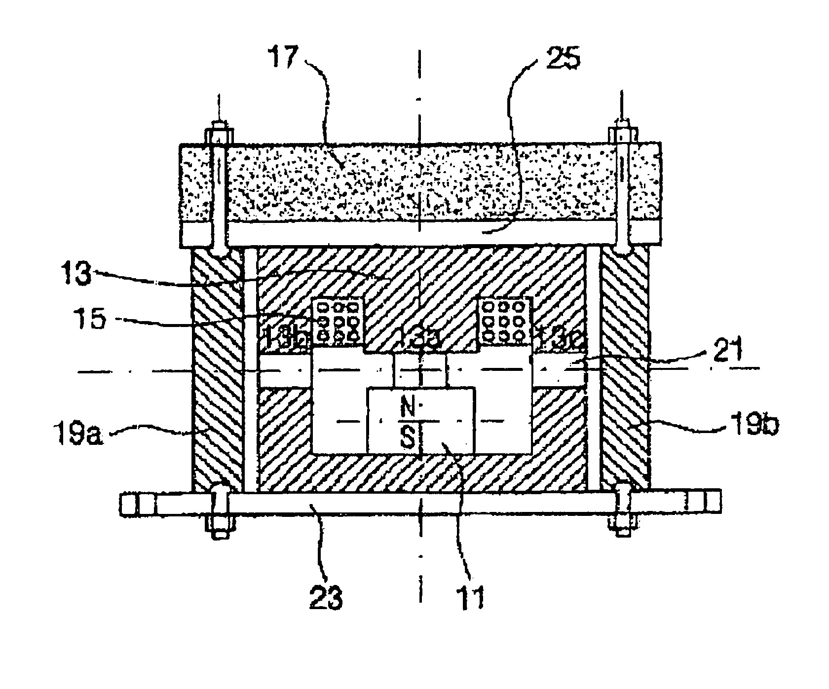
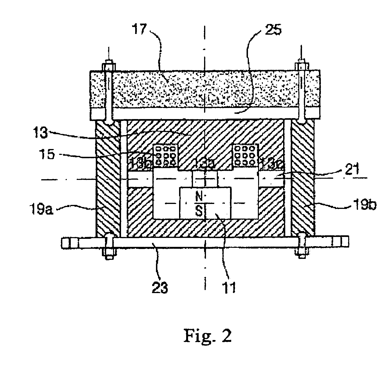
[0017]FIG. 2 is a cross-sectional view showing the preferred embodiment of the present invention. A sound-to-vibration conversion apparatus according to the present invention is roughly composed of a magnet means 11 having an N-pole and an S-pole and being fixed to a housing 23, and an electromagnet 13 arranged to face the N-pole or S-pole of the magnet means 11 and movably fixed to the housing 23. (Even though FIG. 2 shows that the electromagnet 13 faces the N-pole of the magnet means 11, the invention is not limited to this configuration.)

[0018]The housing 23 may be a car seat, a bed, a chair, or any other item to which this apparatus could be adapted. Even though the magnet means 11 can include either a permanent magnet or an electromagnet, in this description a permanent magnet will be typically referred to for convenience.

[0019]As shown in FIG. 2, the electromagnet 13 includes an E-sha


PUM


Abstract

An apparatus adopting an iron core and an inertial mass is disclosed for exerting high power output by converting a sound signal to vibration so as to stimulate the human hearing organs through the bones. A sound-to-vibration conversion apparatus comprises a housing, a permanent magnet having an N-pole and an S-pole, only one pole of which is fixed to the housing, an electromagnet movably installed into the housing faced either the S-pole or N-pole of the permanent magnet, whichever one is not fixed to the housing, and an inertial mass for amplifying the inertial force of reciprocating movement of the electromagnet, so that the housing with the permanent magnet can be vibrated by the electromagnet, whereby the electromagnet vibrates in a reciprocating fashion towards or away from the permanent magnet in accordance with the incubation between the polarity formed at the electromagnet by acoustic signal applied to the electromagnet and either the N-pole or the S-pole of the permanent magnet.

Description


Claims


Application Information

Patent Timeline
Owner TWIN SAVER
Why Eureka
Try Eureka