Heat exchanger with beveled header

Inactive Publication Date: 2006-05-16
DURAMAX MARINE
View PDF18 Cites 5 Cited by
  • Summary
  • Abstract
  • Description
  • Claims
  • Application Information

AI Technical Summary

Benefits of technology

[0033]A further object of the invention is to provide an improved header for a one-piece keel cooler with rectangular coolant flow tubes, by reducing the likelihood of damage to the header from striking debris and underwater objects which could damage the keel cooler.
[0034]It is still another object for the provision of a header for effecting increased turbulent flow of the ambient water flowing between and around the heat transfer tubes.
[0035]It is an additional object to provide an improved header for one-piece keel coolers which enables the anode for such keel coolers to be less likely to strike debris and underwater objects.
[0036]Another object is the provision of a keel cooler having a smaller, and more streamlined profile to reduce drag as the vessel with the keel cooler moves through the ambient water.
[0037]Another object is to provide a header for a one-piece heat exchanger which provides for enhanced heat exchange between the coolant and the ambient cooling medium such as water.
[0038]A general object of the present invention is to provide a one-piece heat exchanger and headers thereof which is efficient and effective in manufacture and use.

Problems solved by technology

However, as the vessel power demand gets larger, ambient water pumped through the engine may continue to provide good cooling of the engine, but also serves as a source of significant contamination damage to the engine.
If raw, ambient water were used to cool the engine, the ambient water would carry debris and, particularly if it is salt water, corrosive chemicals to the engine.
Channel steel has severe limitations: it is very inefficient, requiring a large amount of steel in order to obtain the required cooling effect; it is very expensive to attach to a vessel, since it must be welded to the hull—a very labor intensive operation; since channel steel is very heavy, the engine must be large enough to carry the channel steel, rendering both the initial equipment costs and the operating costs very high; the larger, more powerful engines of today are required to carry added channel steel for their cooling capacity with only a relatively small amount of room on the hull to carry it; the payload capacity is decreased; the large amount of channel steel is expensive; and finally, channel steel is inadequate for the present and future demands for cooling modern day, marine vessels.
The oppositely directed coolant flow in the header causes turbulence, increases pressure drop and reduces coolant flow.
Such upward flow contributes to turbulence in the header, and is inefficient since gravity opposes such flow.
The latter arrangement also results in turbulence in the header, an increase in the pressure drop, and reduces coolant flow.
Furthermore, the beveled end wall is not configured either to direct a substantial amount of coolant into the flow tubes, or to direct a substantial amount of coolant from the flow tubes into the nozzle.
In addition, the perpendicular walls diminish the flow of ambient water between the heat conduction tubes, which reduces or diminishes the amount of heat which can be transferred between the coolant in the tubes and the ambient water.

Method used


Image

  • Heat exchanger with beveled header
  • Heat exchanger with beveled header
  • Heat exchanger with beveled header

Examples


Example

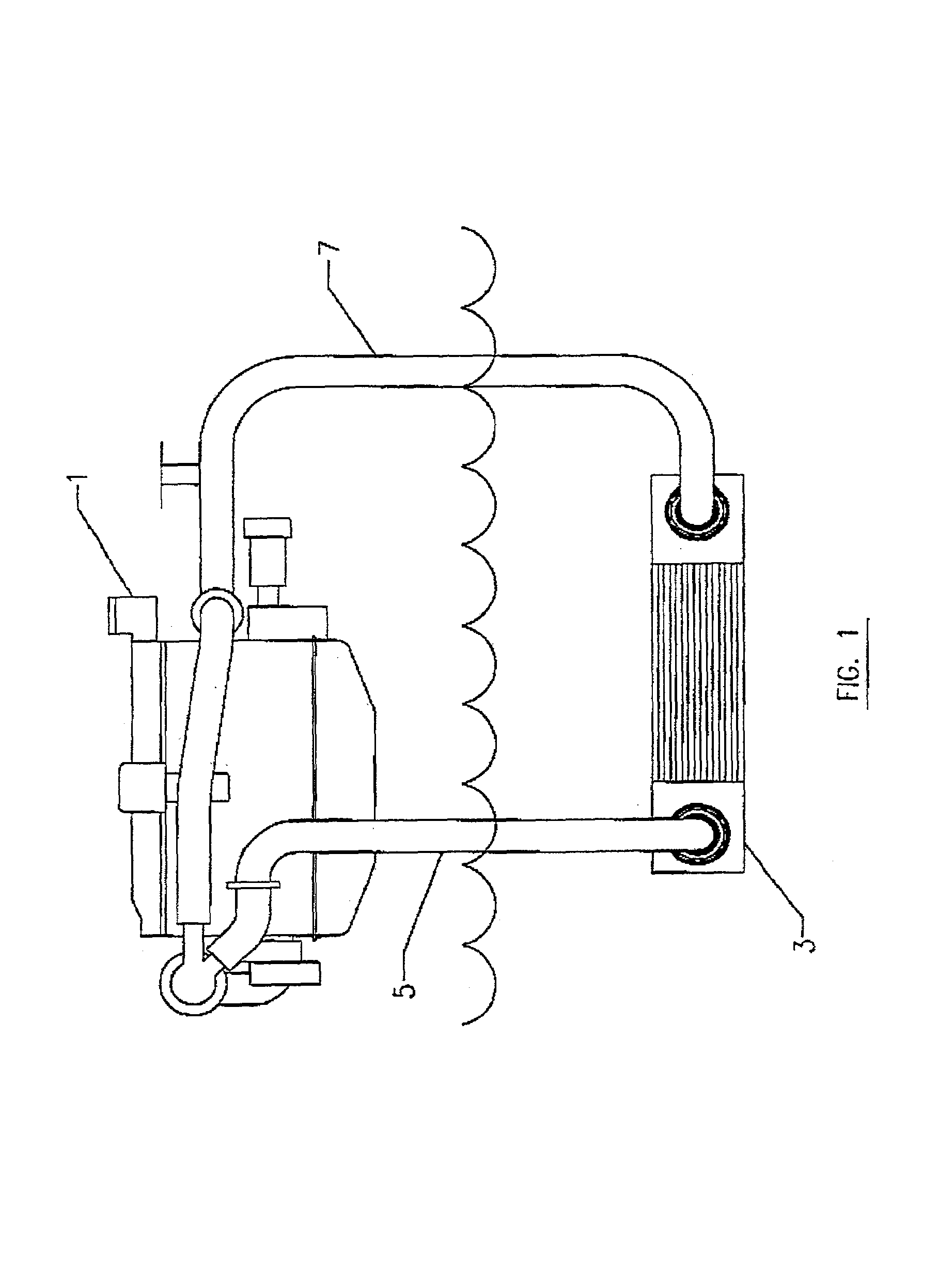
[0059]The fundamental components of a heat exchanger system for a water-going vessel are shown in FIG. 1. The system includes a heat source 1, a heat exchanger 3, a pipe 5 for conveying the hot coolant from heat source 1 to heat exchanger 3, and a pipe 7 for conveying cooled coolant from heat exchanger 3 to heat source 1. Heat source 1 could be an engine, a generator or other heat source for the vessel. Heat exchanger 3 could be a one-piece keel cooler (since only one-piece keel coolers are discussed herein, they are generally only referred to herein as “keel coolers.”) Heat exchanger 3 is located in the ambient water, below the water line (i.e. below the aerated water line), and heat from the hot coolant is transferred through the walls of heat exchanger 3 and expelled into the cooler ambient water.

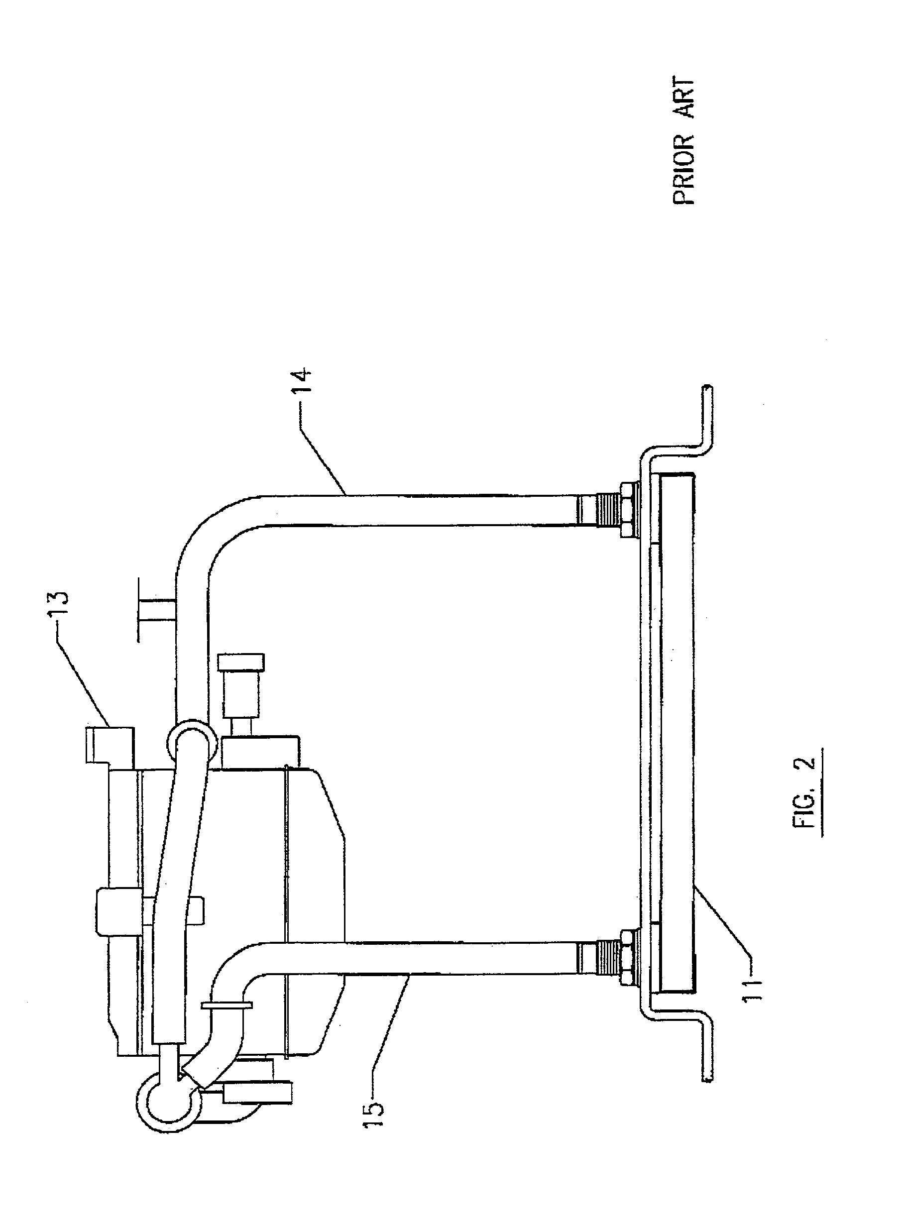
[0060]FIG. 2 shows a heat exchanger 11 mounted on a vessel, for transferring heat from the coolant flowing from an engine or other heat source 13 to the ambient water. Coolant flows from on


PUM


Abstract

A header for a heat exchanger, the header having a beveled closed end portion.

Description


Claims


Application Information

Patent Timeline
Owner DURAMAX MARINE
Why Eureka
Try Eureka