Power failure sensing device and a card reader having a power failure sensing device

a technology of power failure and sensing device, which is applied in the direction of error detection/correction, instruments, power supply for data processing, etc., to achieve the effect of simple and cheap circui

Inactive Publication Date: 2006-07-18
SANKYO SEIKI MFG CO LTD
View PDF17 Cites 1 Cited by
  • Summary
  • Abstract
  • Description
  • Claims
  • Application Information

AI Technical Summary

Benefits of technology

The present invention relates to a sensor used for detecting power failures on electronic devices like smartphones. It uses a special circuit design that allows it to accurately detect when there are no electrical current flow through its input terminals during normal use. This technology makes things easier and more cost-effective than existing methods.

Problems solved by technology

The technical problem addressed in this patent is how to improve the detection of power failures on both the inside and outside of a device without adding extra components or complicated configurations.

Method used


Image

  • Power failure sensing device and a card reader having a power failure sensing device
  • Power failure sensing device and a card reader having a power failure sensing device
  • Power failure sensing device and a card reader having a power failure sensing device

Examples


Embodiment Construction

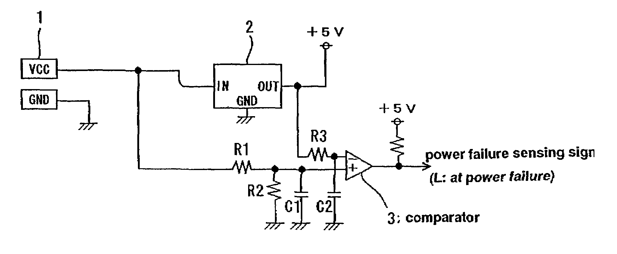
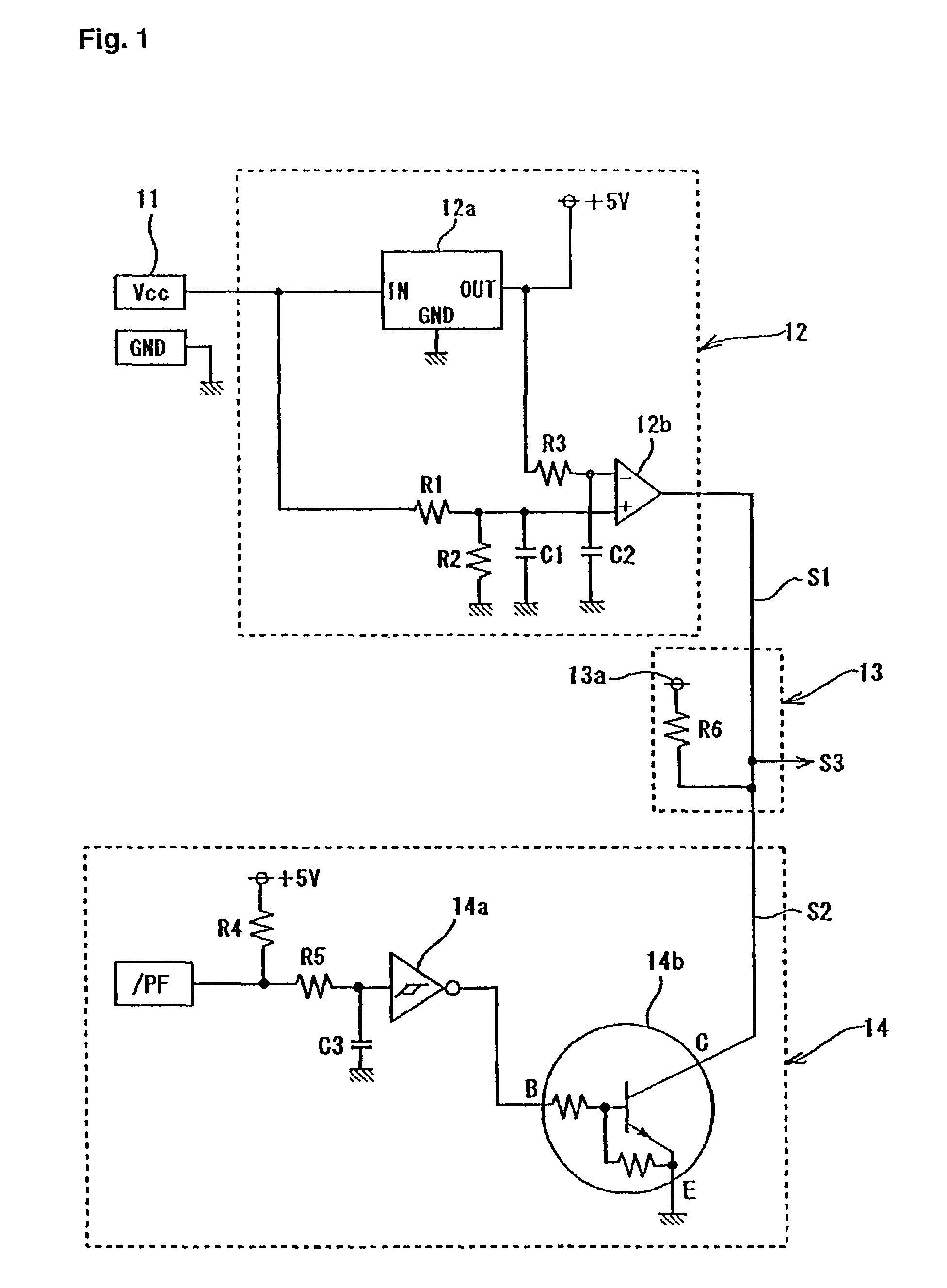
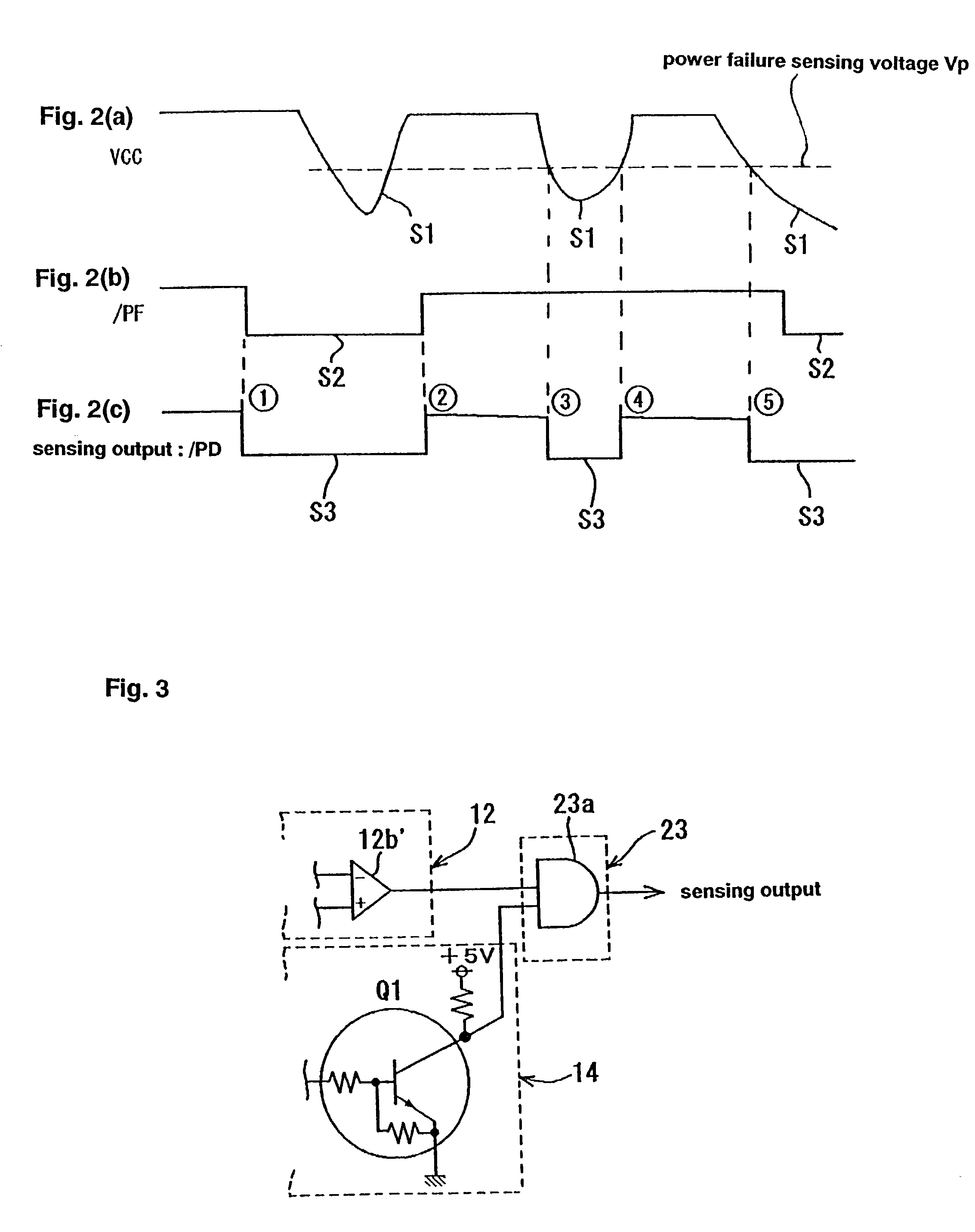
[0018]A power failure sensing device in an embodiment shown in FIG. 1 applies the present invention to a card reader built in as a subordinate device in a cash dispenser as a host external device. The various operations that are carried out in the card reader of a use apparatus as the subordinate device is controlled based on command signals from the cash dispenser as the host external device and Interlocked operations carry out.

[0019]A power failure sensing device provided in the card reader provides a card reader power failure sensing circuit 12 to detect the state of a power failure in an internal electrical power source 11 provided for the card reader. Also, the main unit of the cash dispenser as the host external device provides a host device power failure sensing circuit to detect the state of a power failure of a power source with the main unit which omitted illustration.

[0020]In the card reader power failure sensing circuit 12, at first, an output voltage (24V) from an internal


PUM


Abstract

A power failure detection system for detecting power failures in a cash dispenser machine and in an associated card reader includes an external signal input part for receiving a power failure signal from a first power failure sensing circuit located in a host cash dispenser machine, a card reader associated with the cash dispenser; an internal power source located in the card reader, a second power failure sensing circuit located in the card reader; a power failure signal output part for receiving and processing power failure signals from the external signal input part and from the second power failure sensing circuit. The power failure signal output part contains a circuit to output a final power failure signal if either the card reader or the cash dispenser has a power failure wherein the shape of said final power failure signal indicates whether the card reader or the cash dispenser or both experience a power failure.

Description


Claims


Application Information

Patent Timeline
Owner SANKYO SEIKI MFG CO LTD
Why Eureka
Try Eureka