Transformer inrush current elimination system
a technology of transformer inrush current and elimination system, which is applied in the direction of electric variable regulation, process and machine control, instruments, etc., can solve the problems of excessive inrush current, excessive inrush current, and deviation of mechanical closing time and influence of pre-arc of circuit breaker, so as to prevent excessive inrush current generation
- Summary
- Abstract
- Description
- Claims
- Application Information
AI Technical Summary
Benefits of technology
Problems solved by technology
Method used
Image

Examples
embodiment 1
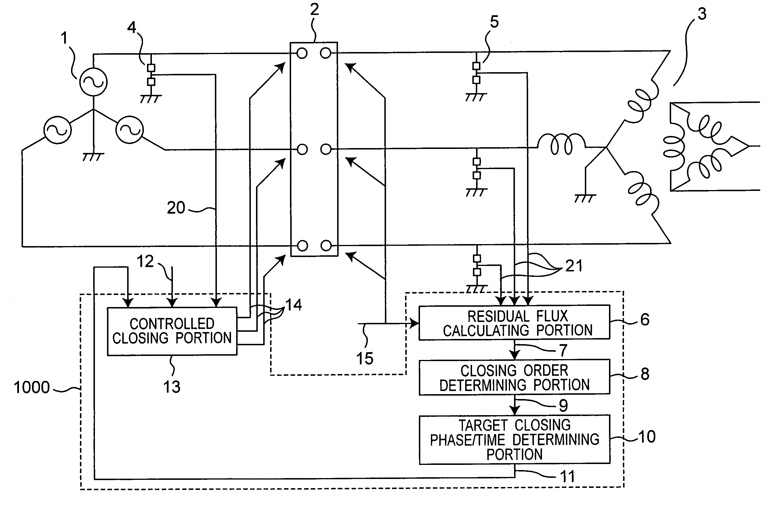
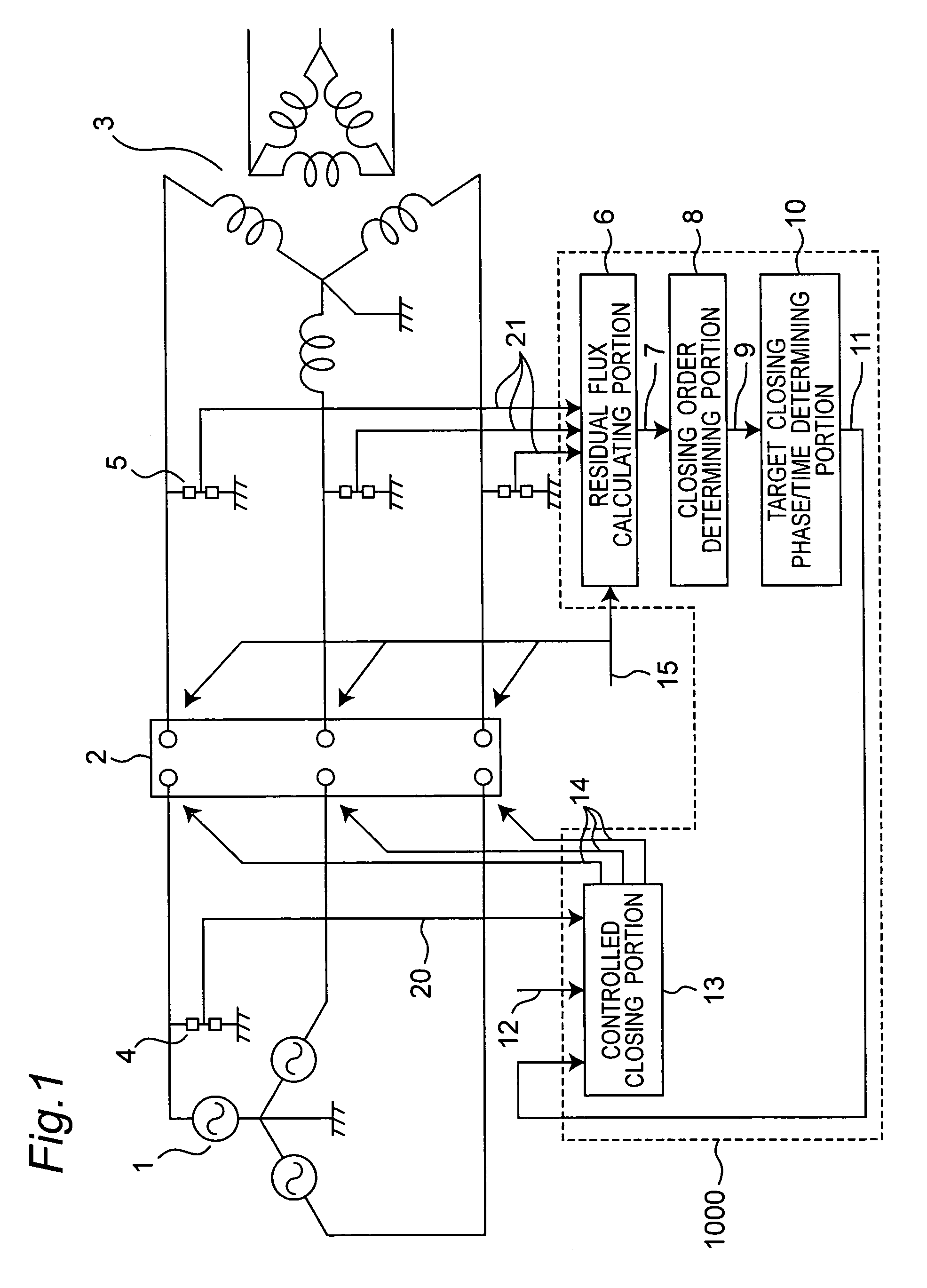
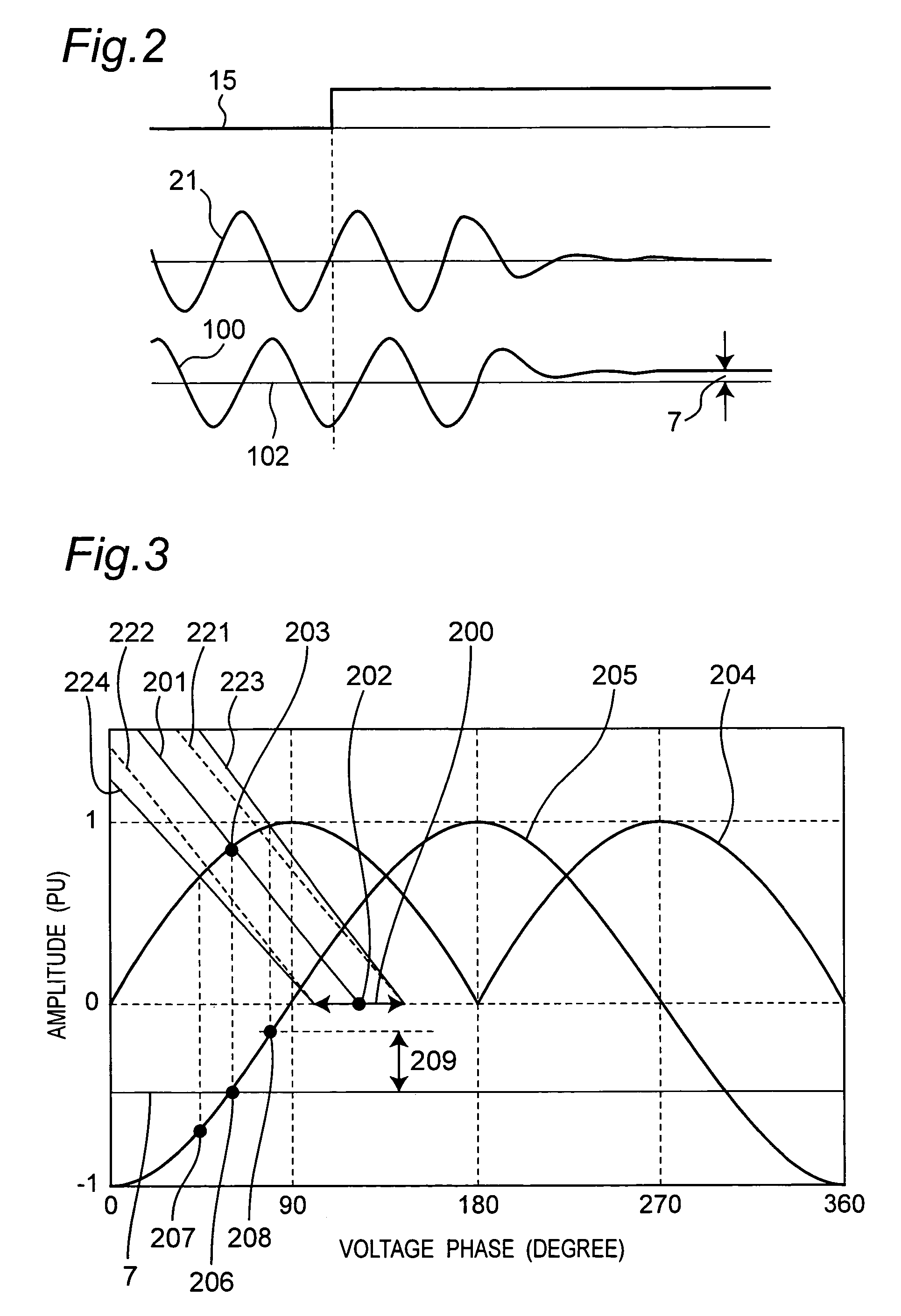
[0038]FIGS. 1 to 4 are drawings for explaining an embodiment 1 of a transformer inrush current elimination system (hereinafter, briefly referred to as “inrush current elimination system” or simply “inrush current elimination system” by omitting “transformer”). More specifically, FIG. 1 is a block diagram showing a main construction of an inrush current elimination system including a three-phase transformer, a three-phase circuit breaker together with showing signals and data flows. FIG. 2 is a timing chart showing a relationship among a opening command signal, a transformer voltage and a flux signal. FIG. 3 shows phase characteristics for explaining an error in an applied flux. FIG. 4 is a characteristic diagram showing one example of an applied-flux error in each contact-close phase (voltage phase).
[0039]A three-phase transformer 3 includes a primary winding having a star connection structure and a secondary or tertiary winding having a triangle connection structure, where an core is
embodiment 2
[0098]FIG. 5 shows a transformer inrush current elimination system in accordance with an embodiment 2 of the present invention. More specifically, FIG. 5 is a circuit block diagram showing a structure of main portions of an inrush current elimination system which includes a three-phase transformer, a three-phase circuit breaker, together with flows of signals and data.
[0099]In this embodiment, a controlled opening portion 616 is added to the structure of the embodiment 1 shown in FIG. 1. The controlled opening portion 616 generates a circuit-controlled opening signal 17 for controlling the opening process of each phase of the three-phase circuit breaker 2. In the structure shown in FIG. 2, a transformer voltage 621 of the standard phase is measured by a transformer voltage measuring means 605, while a residual flux 607 of the standard phase is calculated by a residual flux calculating portion 606. Here, since the standard phase is used as the first closing phase, the closing order dete
embodiment 3
[0112]An embodiment 3 of the present invention will be described below with reference to FIGS. 1 and 6. FIG. 6 is a characteristic drawing that shows a relationship between the minimum energization flux error and the respective residual fluxes in a transformer inrush current elimination system having the same construction as that shown in FIG. 1 of the embodiment 1. In FIG. 6, the unit of the axis of ordinates and the axis of abscissas is PU, and, in the same manner as the axis of ordinates in FIG. 3, the amplitude of the flux of the three-phase transformer 3 upon application of a normal voltage is standardized as 1PU.
[0113]In the embodiment 1, the closing order determining portion 8 determines the first closing phase among three-phases, by preparing the phase having the greatest absolute value of the residual flux 7 calculated by the residual flux calculating portion 6 as the first closing phase. Whereas, in the present embodiment 3, with respect to each phase, a closing phase that ma
PUM
 Abstract
Description
Claims
Application Information
 - R&D Engineer
- R&D Manager
- IP Professional
- Industry Leading Data Capabilities
- Powerful AI technology
- Patent DNA Extraction
Browse by: Latest US Patents, China's latest patents, Technical Efficacy Thesaurus, Application Domain, Technology Topic.
© 2024 PatSnap. All rights reserved.Legal|Privacy policy|Modern Slavery Act Transparency Statement|Sitemap