Both-way movable body driving mechanism and elevator using the same

a reciprocating motion and mechanism technology, applied in the direction of mine lifts, hoisting equipment, transportation and packaging, etc., can solve the problems of inability to reduce the weight of cage b>1/b>, difficulty in reducing cage weight, etc., and achieve the effect of small weigh

Inactive Publication Date: 2007-02-20
FUJITEC CO LTD
View PDF17 Cites 19 Cited by
  • Summary
  • Abstract
  • Description
  • Claims
  • Application Information

AI Technical Summary

Benefits of technology

The present invention provides an improved lifting machine that uses a small motor instead of a large pulley system to move the cage. It achieves this by using a special type of belt called a tension member that helps it work better with its own weight.

Problems solved by technology

The technical problem addressed in this patent is how to provide a more efficient and effective way to prevent the rope from slippaging during operation of a hoist system used in lifts, particularly in smaller buildings.

Method used


Image

  • Both-way movable body driving mechanism and elevator using the same
  • Both-way movable body driving mechanism and elevator using the same
  • Both-way movable body driving mechanism and elevator using the same

Examples


Embodiment Construction

[0060]Embodiments of the invention will be described below in detail with reference to the drawings. First, a description will be given of an elevator apparatus wherein a drive device of the straight drive type is used as a drive device for driving ropes, serving as tension members, by frictional contact therewith, i.e., by pressing a straight region of each rope. Subsequently, a description will be given of an elevator apparatus wherein a drive device of the circular-arc drive type is used for driving ropes as reeved around a sheave by pressing a circular-arc region of each rope against the sheave.

Apparatus Comprising Drive Device of Straight Drive Type

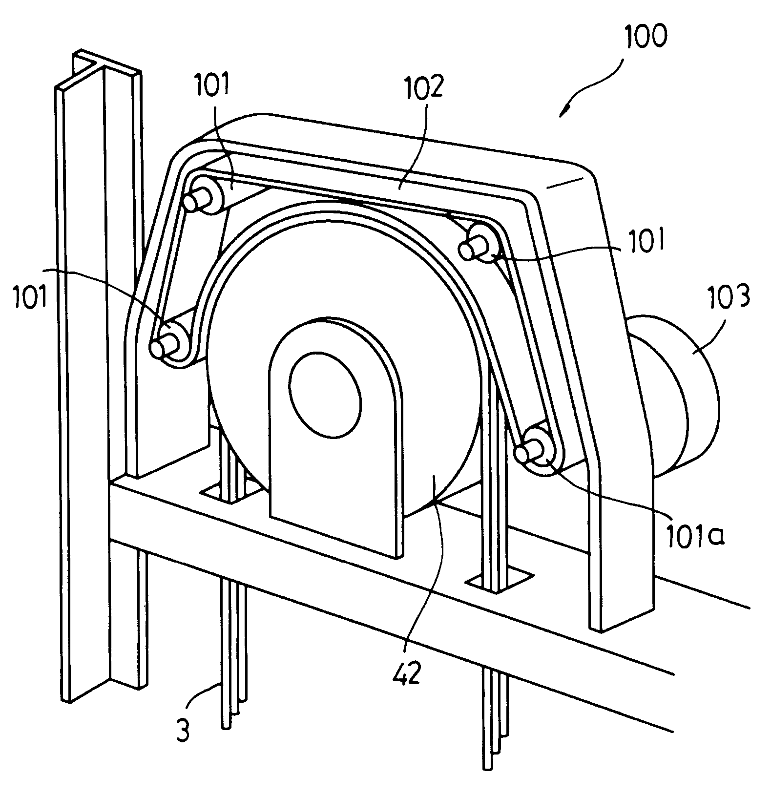
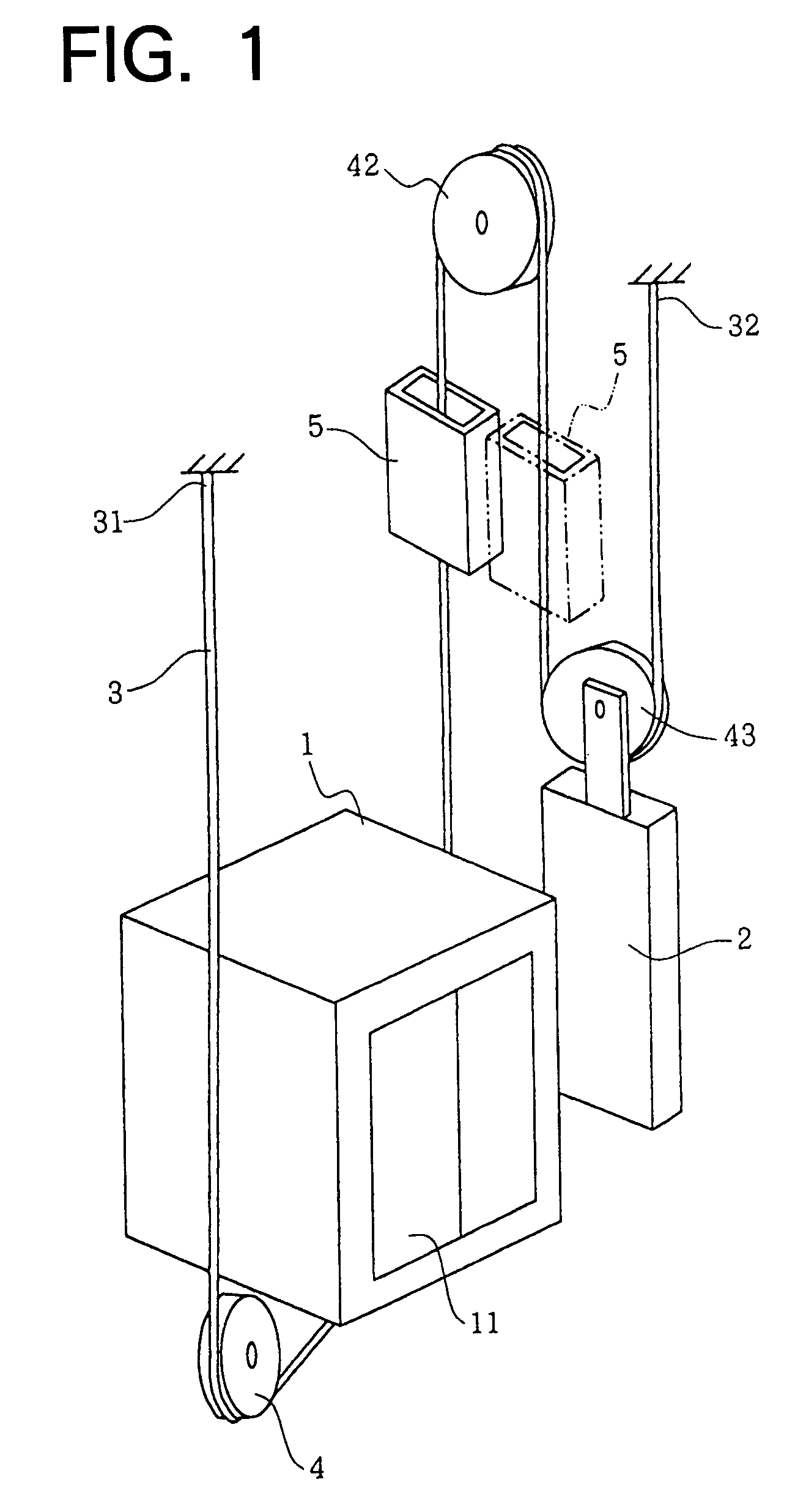
[0061]FIG. 1 shows the basic construction of an elevator apparatus of the invention wherein a drive device of the straight drive type is used. As illustrated, a rope 3 extends as reeved around a plurality of sheaves, such as a sheave 42 provided at a specified position within a path of movement of the elevator and sheaves 4, 43 attached


PUM


Abstract

The invention provides an elevator apparatus comprising a cage 1 disposed inside a path of upward or downward movement vertically movably, a counterweight 2 vertically movable with the upward or downward movement of the cage 1, and a lift drive mechanism for driving the cage 1 upward or downward. The drive mechanism comprises a sheave 42 disposed inside the path, ropes 3 extending along a route around the sheave 42, and a drive device 5 in engagement with the ropes 3. The drive device 5 comprises a belt transmission provided alongside the ropes 3 and revolvingly movable along the rope extension route, a mechanism for pressing a belt surface of the belt transmission into contact with the ropes 3, and a drive motor for driving the belt transmission. The cage can be driven upward or downward without using any traction sheave, while the cage can be reduced in weight.

Description


Claims


Application Information

Patent Timeline
Owner FUJITEC CO LTD
Why Eureka
Try Eureka