Digital synchronizing generator

Inactive Publication Date: 2007-09-11
GRASS VALLEY U S
View PDF39 Cites 4 Cited by
  • Summary
  • Abstract
  • Description
  • Claims
  • Application Information

AI Technical Summary

Problems solved by technology

Such a phase difference can adversely affect the processing of such signals.
However, the implementation of an analog sync generator requires a large number of commercially available analog components and extensive calibration to guarantee repeatable performance.
In addition, color-frame sequencing is difficult to implement in an analog sync generator.
In this regard, burst-l

Method used


Image

  • Digital synchronizing generator
  • Digital synchronizing generator
  • Digital synchronizing generator

Examples


Embodiment Construction

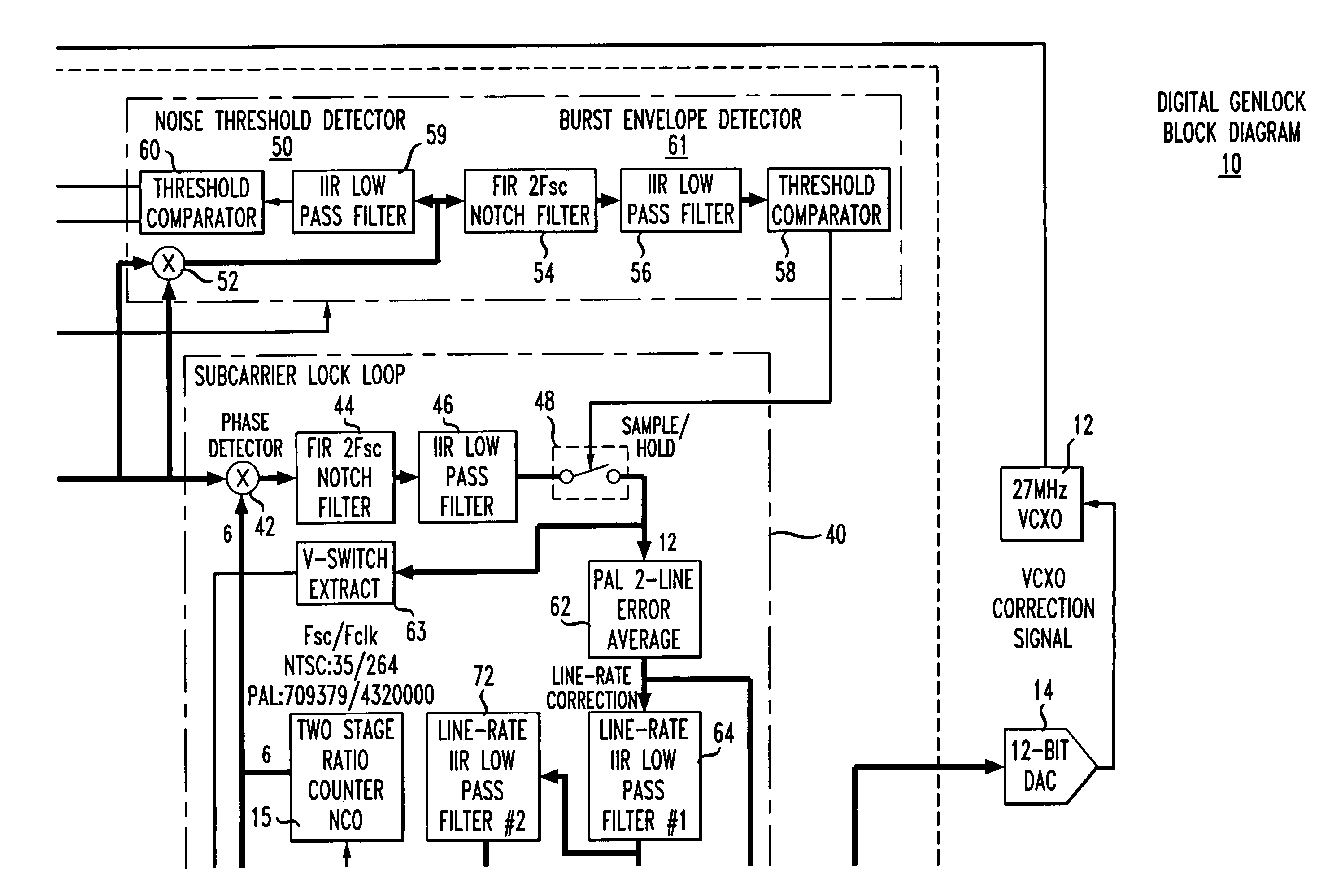
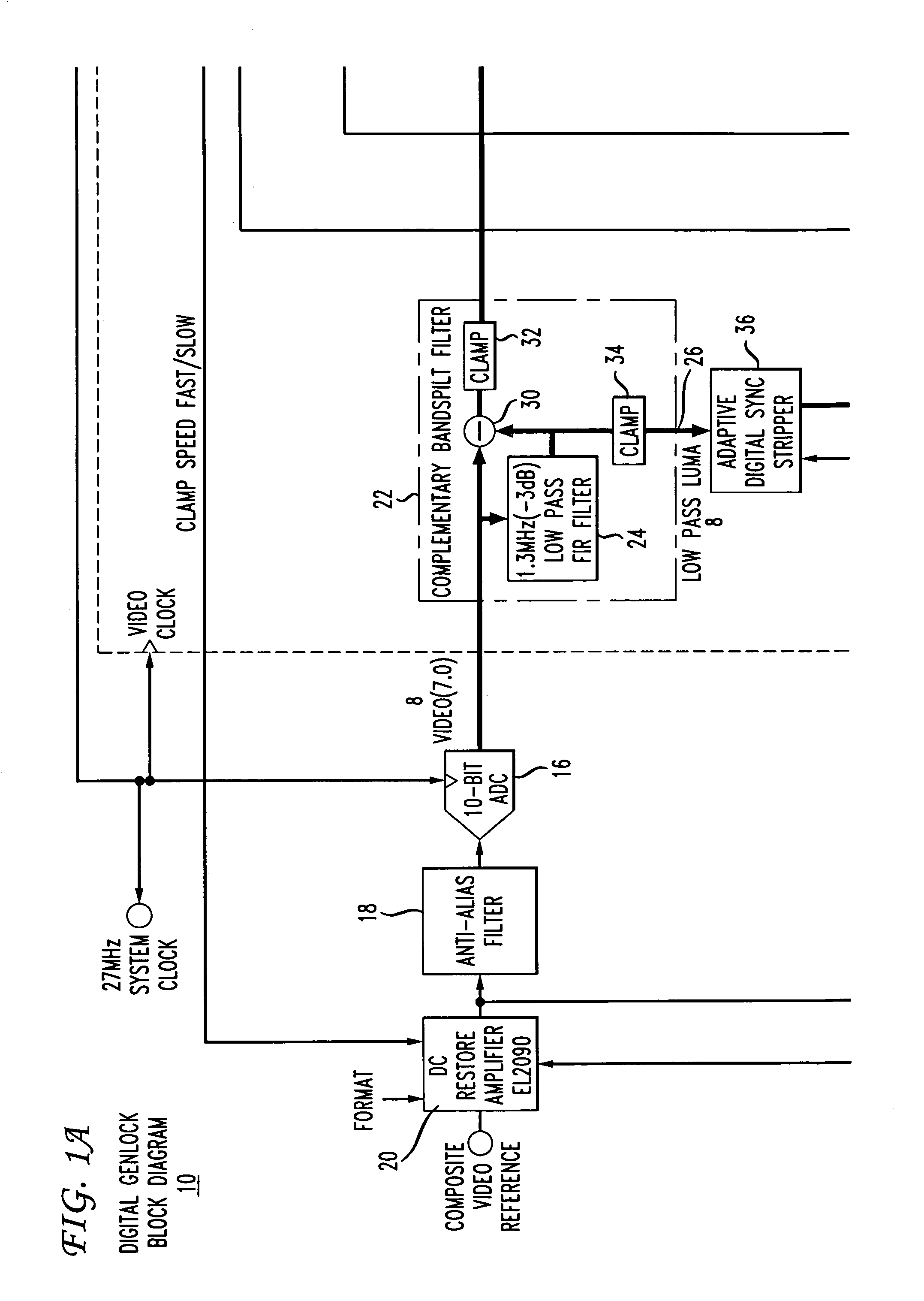
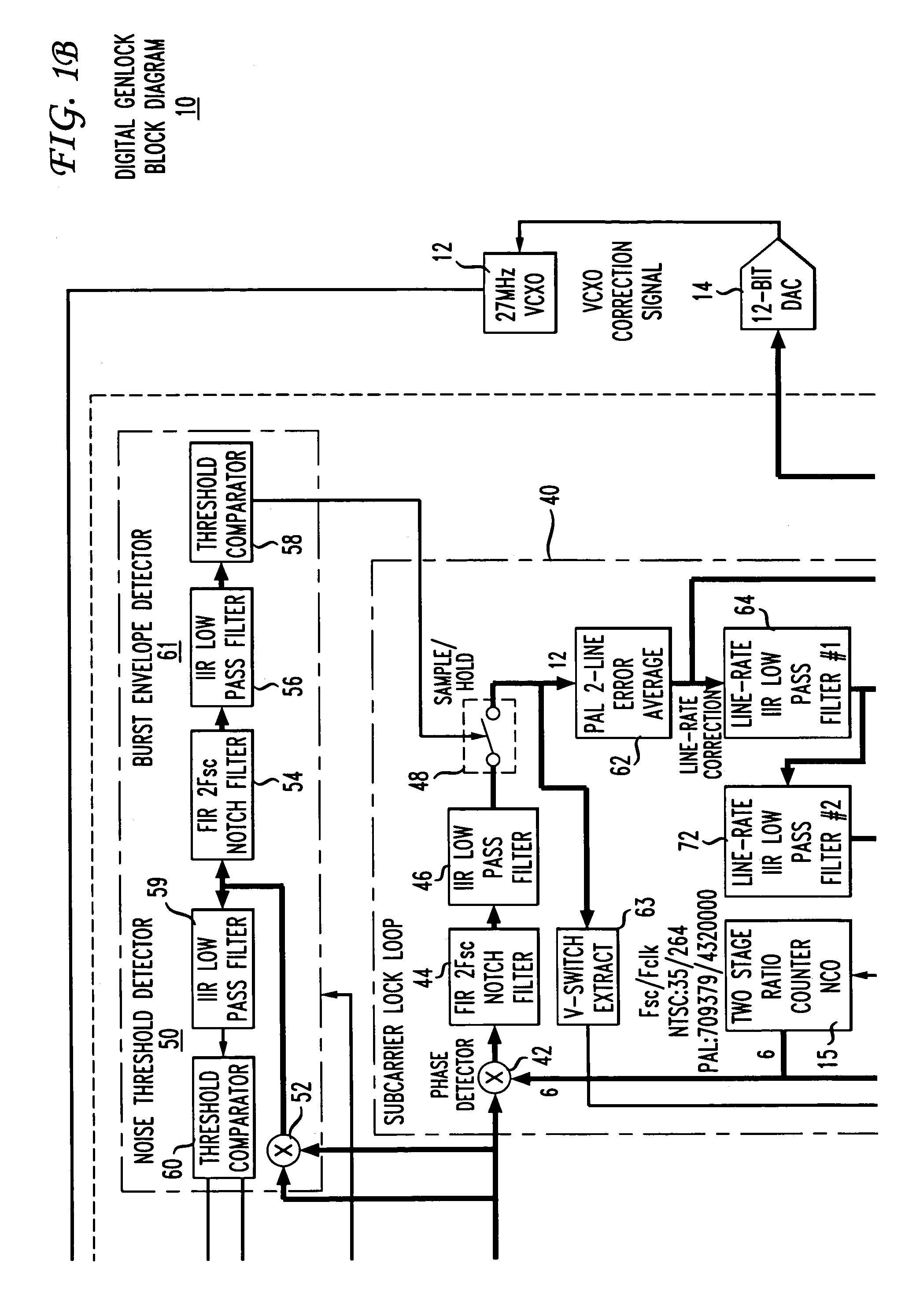
[0015]FIG. 1 depicts a block schematic diagram of an illustrative embodiment of a digital synchronizing generator 10 in accordance with the present principles. The generator 10 includes a Voltage Controlled Oscillator (VCXO) 12 that generates a clock frequency of 27 MHz for locking to an incoming video signal for synchronizing one or more video sources (not shown). The VCXO 12 responds to a VCXO correction signal generated by Burst Lock / Color framing circuit 13 and converted from a digital to an analog signal by a Digital-to-Analog Converter (DAC) 14 prior to receipt at the VCXO. As described below, the framing circuit 13 generates the VCXO correction signal in accordance with a static phase offset from an ideal 90° phase offset between the digitized burst component of the incoming video signal and a numerically controlled oscillator clock 15 described in greater detail below. In this way, the 27 MHz. clock signal becomes locked to the incoming video signal.

[0016]The 27 MHz. clock si


PUM


Abstract

A sync generator (genlock) (10) for frequency and phase locking an incoming video signal to a system clock (12) includes a digitizer (16, 22) for digitizing the incoming video signal to yield a digitized color sub-carrier burst component. A numerically controlled oscillator (15) clocked by the system clock generates a phase lock reference signal for locking to the incoming video signal. Phase detection means logic unit (42, 74) sense a static phase offset magnitude from an ideal 90° phase offset between the digitized color sub-carrier burst component and the numerically controlled oscillator output signal. In accordance with the sensed static offset, a static phase error nulling circuit (70) generates a compensating offset in accordance for input to the system clock (27) to drive the static offset to zero, thus achieving frequency and phase locking. A color frame logic unit (78) determines the color frame sequence for the purpose of resetting the NCO and generating a color frame pulse marking the start of the period sequence.

Description


Claims


Application Information

Patent Timeline
Owner GRASS VALLEY U S
Why Eureka
Try Eureka