Pipe inspection system with selective image capture

a technology of image capture and inspection system, applied in the field of electrical and mechanical systems and methods, can solve problems such as disorientation of video images, and achieve the effect of improving communication and enhancing imaging capabilities

Active Publication Date: 2013-03-12
SEEKTECH
View PDF5 Cites 53 Cited by
  • Summary
  • Abstract
  • Description
  • Claims
  • Application Information

AI Technical Summary

Benefits of technology

The technical effect that this invention provides for better image quality during pipes testing by providing an electronic device called a video recorder (VTR) attached to it's cameras. This allows them to capture images from inside the pipeline without being obstructed or affected by other things around them.

Problems solved by technology

This technical problem addressed in this patents relates to improving visual examination techniques during the process of inserting tubular objects into concrete pipelines due to their potential damage caused by environmental factors like soil pressure changes over time. Current methods involve manually pushing catheters along while visually observing them using videos captured via cameras attached directly onto the pipeline walls. However, current solutions require expensive equipment and can lead to errors even though they were initially installed properly. There has therefore existed a demand for improved ways to detect cracks and defects within steel pipings without requiring costly repairs.

Method used


Image

  • Pipe inspection system with selective image capture
  • Pipe inspection system with selective image capture
  • Pipe inspection system with selective image capture

Examples


Embodiment Construction

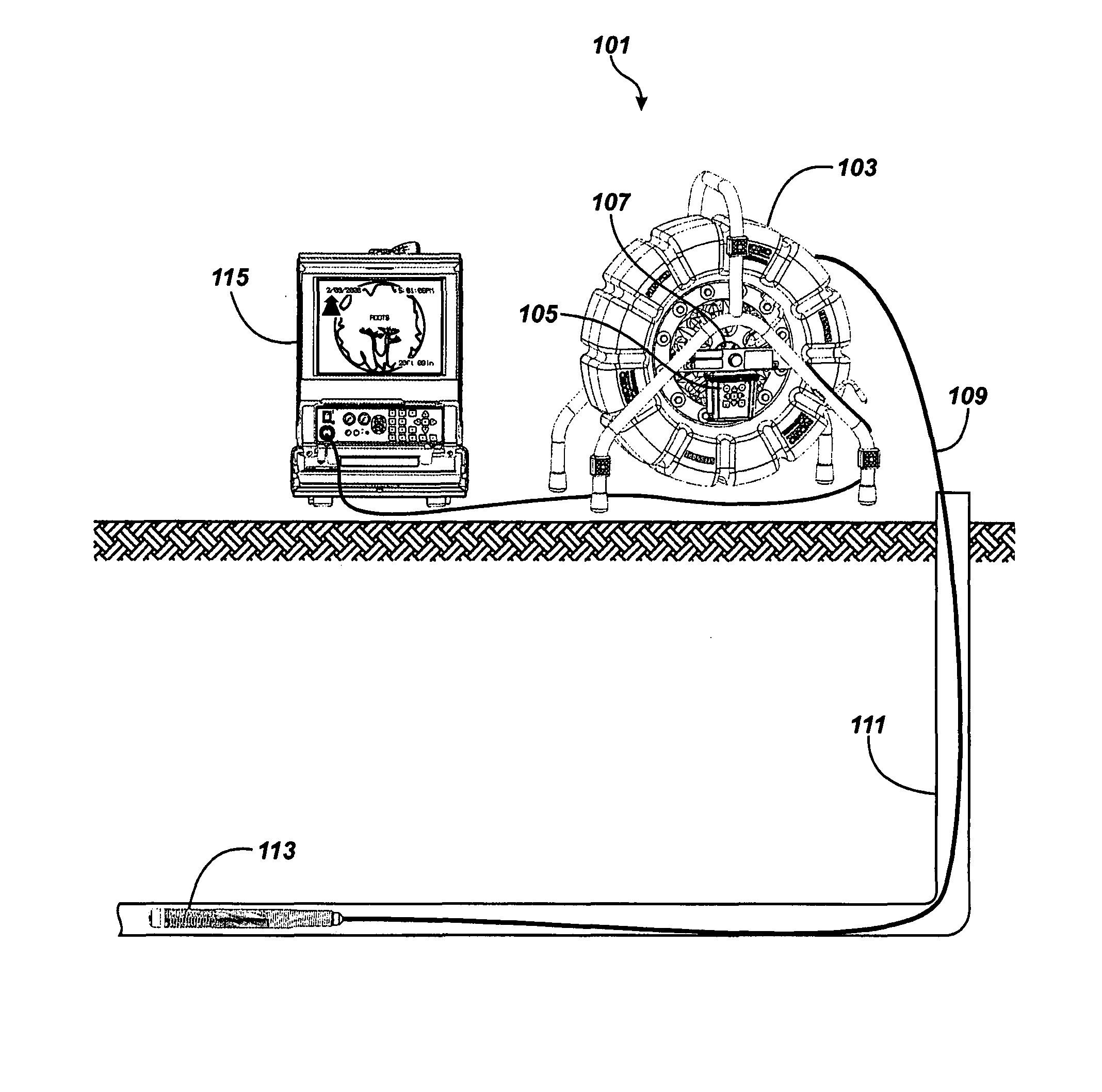
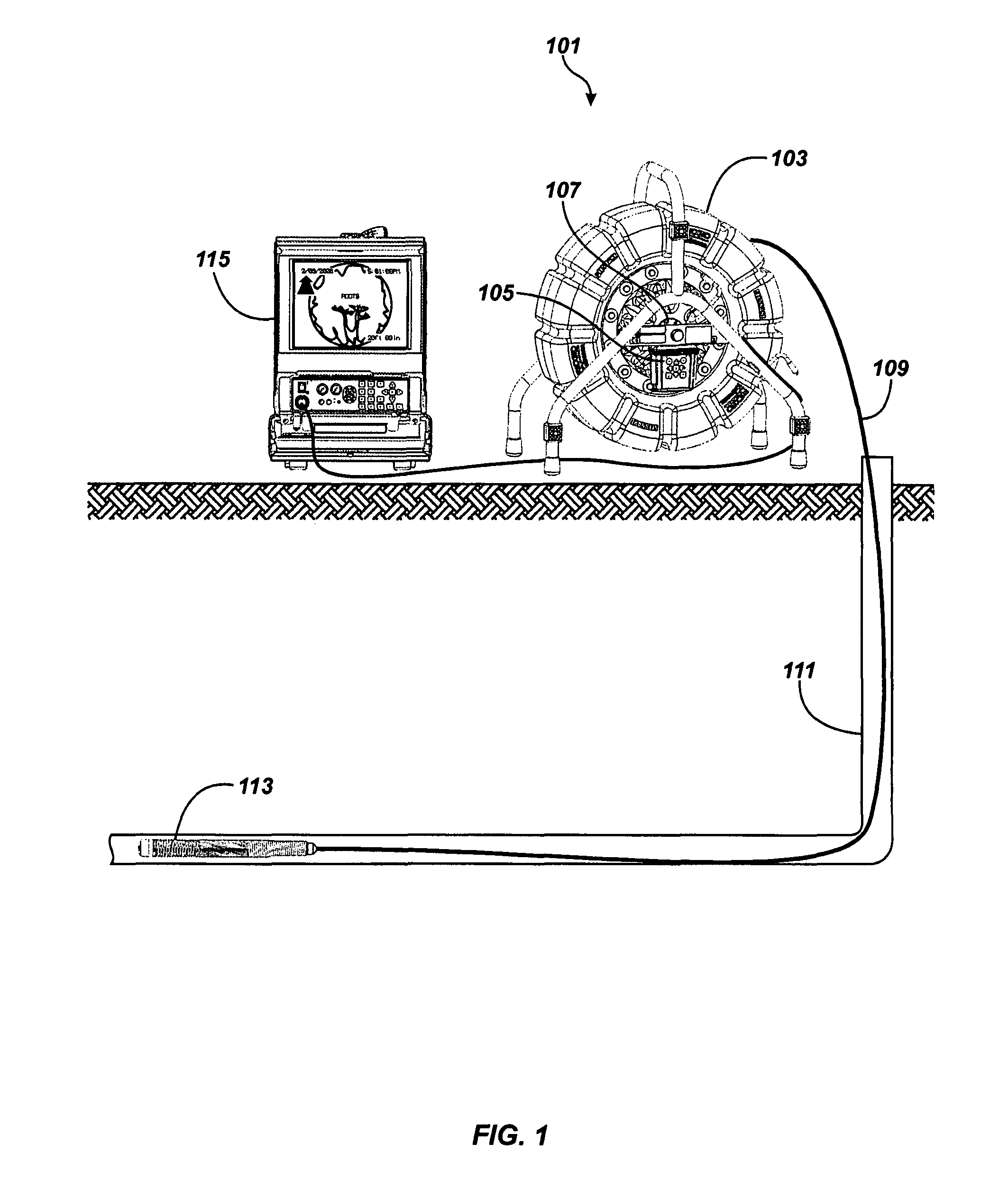
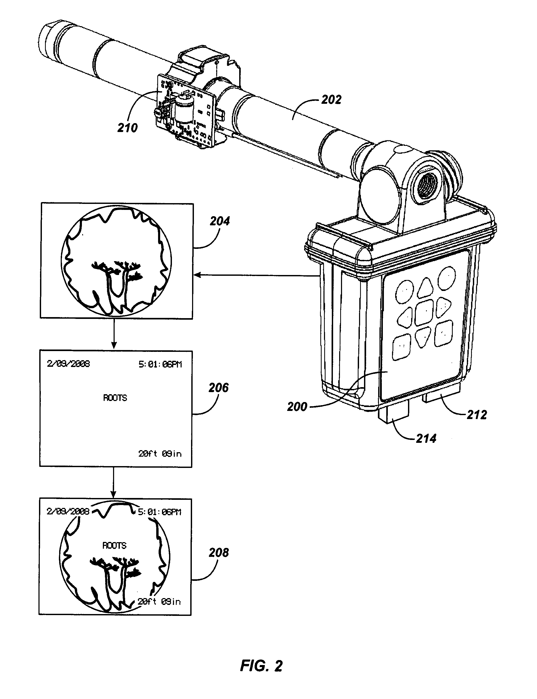
[0022]In one embodiment the present invention provides a pipe inspection system that automatically captures images at user-defined increments of distance traveled down the pipe, as well as display overlays. The overlays can indicate the current distance measurement and direction of travel (downward or upward) of the camera head in the pipe being inspected. It additionally provides advantages in managing images, adding comments and date stamps to images, and storing images to removable media at user discretion.

[0023]The present invention also provides a pipe inspection system that allows for storage of images in a readily removable portable storage device. The storage device can be used to transfer images showing their measured distance or location to a portable printer for immediate inclusion in an inspection debrief or report, using a conventional portable computer. Electronic transfer through wireless, USB cable, Fire-wire or other means may be used.

[0024]In another embodiment of the


PUM


Abstract

Various pipe inspection systems include a camera head operatively connected to the distal end of a push-cable. Images may be automatically captured at predetermined distances of travel, or may be automatically captured based on the output signals from the auto-focus, auto-exposure and/or auto-white balance engines indicating, for example, that the camera motion within the pipe is substantially zero. Images may be captured in an automatic mode at predetermined intervals as the camera head travels within the pipe or in an override mode initiated by operator command. The system may include a data transmission circuit that transmits data between a plurality of nodes at a frequency that does not substantially interfere with a normal base band video transmission frequency.

Description


Claims


Application Information

Patent Timeline
Owner SEEKTECH
Why Eureka
Try Eureka