Fish alert device for a fishing rod

a technology for alerting devices and fishing rods, which is applied in the field of fishing rod alert devices, can solve the problems of fishing rod loss, fishing rod loss, and long periods of holding a rod while nothing is happening,

Inactive Publication Date: 2016-07-19
HARVEY TIMOTHY P
View PDF22 Cites 0 Cited by
  • Summary
  • Abstract
  • Description
  • Claims
  • Application Information

AI Technical Summary

Benefits of technology

This new design allows for better monitoring during angling without being attached to any part or equipment around it. It uses a special mechanism called a balance beam with two parts - one connected to the main body of the apparatus while another connects to a counterweight located near its end. A spring-loaded ring acts like a valve when there're no motion happening inside them. By moving backward through these movements, which occur within certain limits, the system can trigger alarms if they happen. Overall, this technology helps prevent damage caused by unnatural behavior such as sinking hooks or getting stuck between bait lines.

Problems solved by technology

The technical problem addressed in this patented text relates how current methods are limited because they require constant attention from fishers who want them to stay still during the process. This can be annoying at best but also causes damage overtime due to keeping one's hands busy with other tasks such as carrying tools around without being able to see what happens next.

Method used


Image

  • Fish alert device for a fishing rod
  • Fish alert device for a fishing rod
  • Fish alert device for a fishing rod

Examples


Embodiment Construction

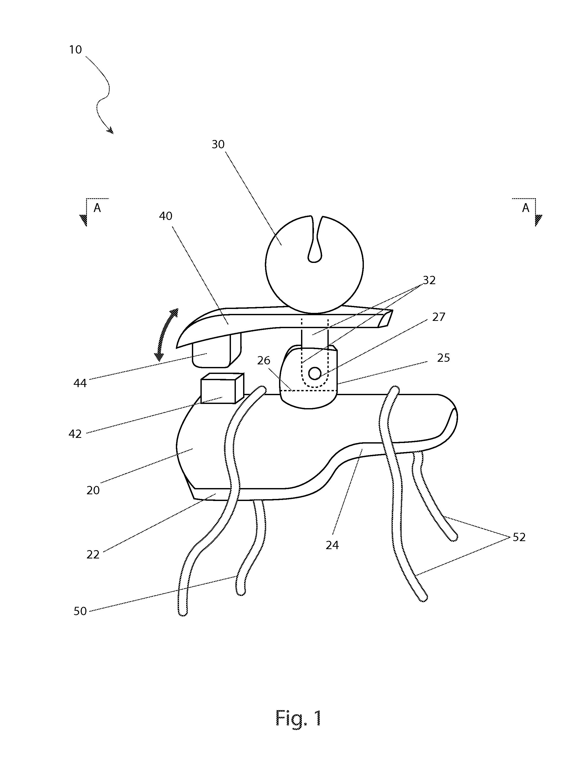
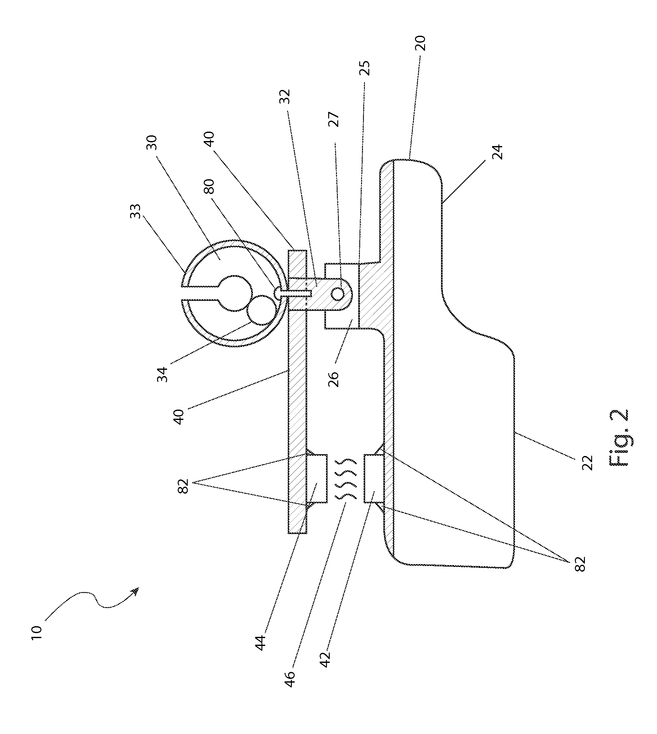
[0029]The best mode for carrying out the invention is presented in terms of its preferred embodiment, herein depicted within FIGS. 1 through 3. However, the invention is not limited to the described embodiment, and a person skilled in the art will appreciate that many other embodiments of the invention are possible without deviating from the basic concept of the invention and that any such work around will also fall under scope of this invention. It is envisioned that other styles and configurations of the present invention can be easily incorporated into the teachings of the present invention, and only one particular configuration shall be shown and described for purposes of clarity and disclosure and not by way of limitation of scope.

[0030]The terms “a” and “an” herein do not denote a limitation of quantity, but rather denote the presence of at least one of the referenced items.

[0031]The present invention describes a fish alert device for a fishing rod (herein described as the “devic


PUM


Abstract

A fish alert device for a fishing rod provides a means to alert a fisherman of a fish on the line. The device includes an alert bell and a housing which is adaptable to an existing fishing rod that provides an alarm sound upon catching a fish. The device allows a user to cast and re-cast without needing to remove the device.

Description


Claims


Application Information

Patent Timeline
Owner HARVEY TIMOTHY P
Why Eureka
Try Eureka