Color calibration method of camera module

a camera module and color calibration technology, applied in the field of color calibration, can solve the problems of poor stability high maintenance cost of the standard lighting cabinet, and time-consuming process, and achieve high automation degree, high flexibility and adaptability, and high convenience in color changing

Active Publication Date: 2016-12-06
THOUSAND LIGHTS LIGHTING CHANGZHOU LTD
View PDF2 Cites 8 Cited by
  • Summary
  • Abstract
  • Description
  • Claims
  • Application Information

AI Technical Summary

Benefits of technology

This patent describes a method for accurately measuring colors in a way that can be done quickly and easily. It involves setting up parameters for different colored samples based on their respective standards and capturing images with a special device. These captured data are then used to create a mathematical equation called a calibration model. By comparing these models, it becomes possible to adjust the colors of the original image beforehand. Overall, this technology allows for precise and efficient color change and calibration while maintaining ease of use.

Problems solved by technology

The technical problem addressed in this patent text relates to improving the accuracy and efficiency of color calibrating cameras used in mobile internet applications. Traditional methods require expensive equipment or complicated procedures that may take longer than necessary.

Method used


Image

  • Color calibration method of camera module
  • Color calibration method of camera module
  • Color calibration method of camera module

Examples


embodiment i

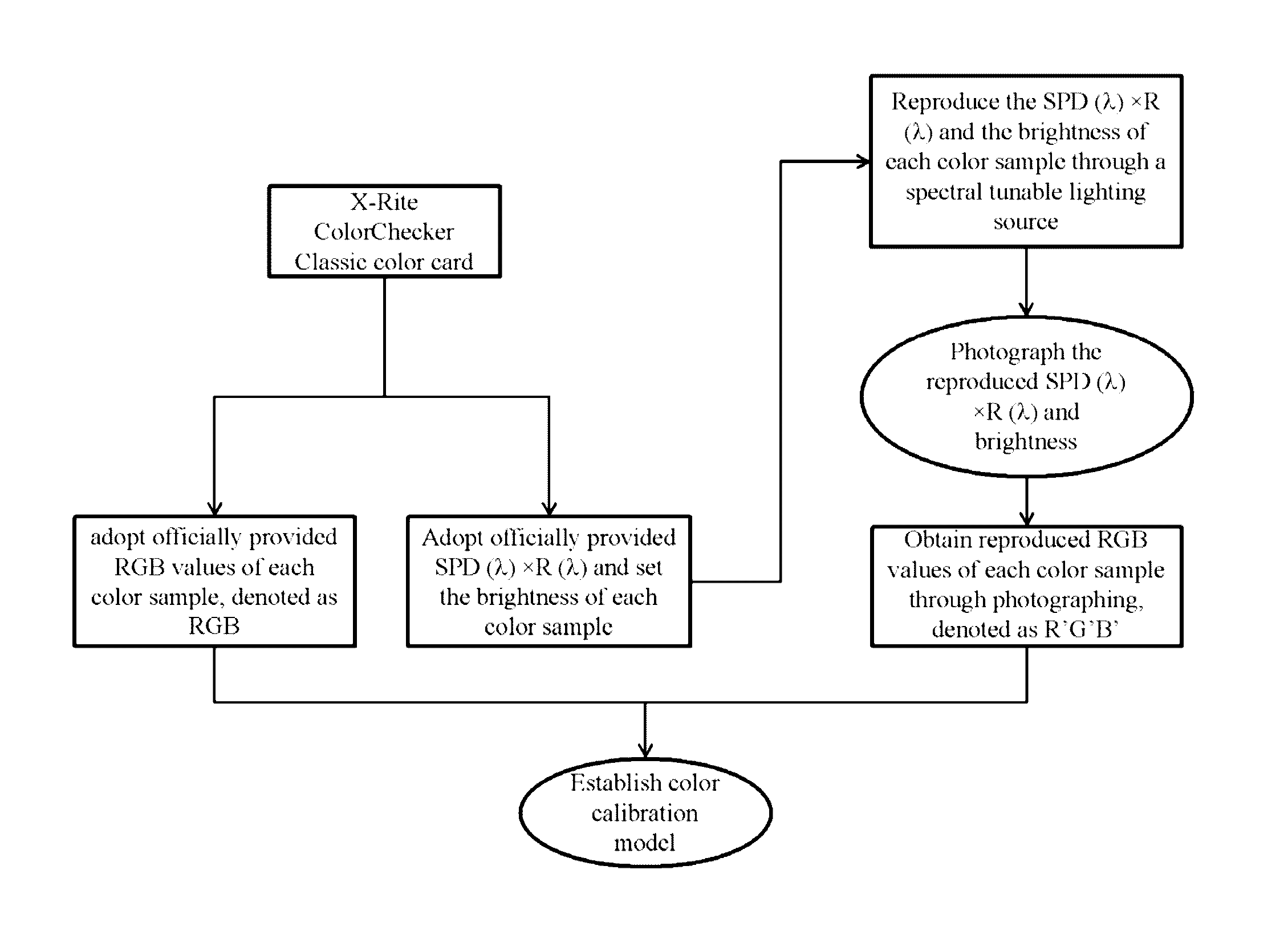
[0032]Taking the setting of RGB values, SPD (λ)×R (λ), brightness of each color sample and a Canon EOS 650D three-channel RGB camera as an example, the flowchart is as shown in FIG. 1, and the specific steps are as follows:

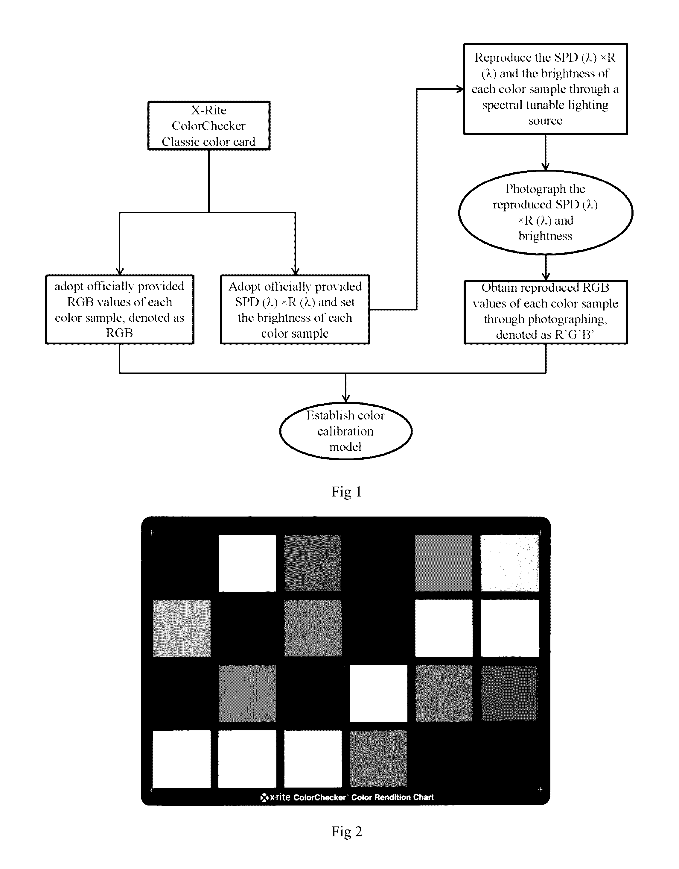
1) adopting a 24-color X-Rite ColorChecker Classic color chart as shown in FIG. 2;

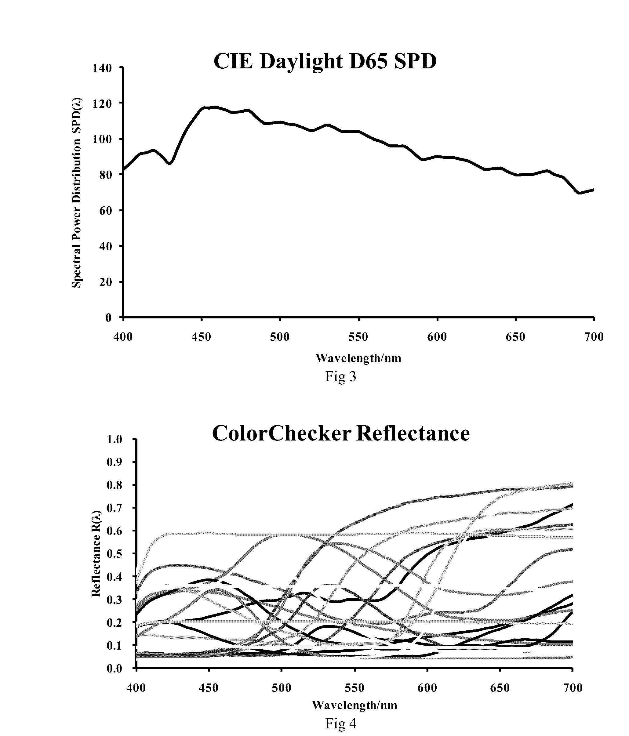
[0033]2) adopting officially provided RGB values of each color sample in the standard color chart as reference parameter values; meanwhile, adopting the multiplication result of spectral power distribution SPD (λ) of standard daylight D65 defined by International Commission on illumination and officially provided spectral reflectance R (λ) of each color sample of the standard color chart as SPD (λ)×R (λ) (as shown in FIG. 3 and FIG. 4); setting the brightness of each color sample;

3) reproducing the SPD (λ)×R (λ) and the brightness of each color sample through a spectral tunable lighting source;

4) sequentially photographing the each reproduced SPD (λ)×R (λ) and brightness of each color s

embodiment ii

[0034]Taking obtaining RGB values of each color sample of a Canon EOS 650D three-channel RGB camera through photographing and measurement and obtaining the SPD (λ)×R (λ) and the brightness of each color sample through measurement as an example, the flowchart is as shown in FIG. 9, and the specific steps are as follows:

1) adopting a 24-color X-Rite ColorChecker Classic standard color chart;

[0035]2) as shown in FIG. 10, laying the color chart in the standard lighting cabinet using 0 / 45 geometry with daylight D50, photographing the color chart through a Canon EOS 650D single-lens reflex camera (f-number 5.6, exposure time 1 / 60 and ISO100), and obtaining the preference RGB values of each color sample in the color chart after processing; meanwhile, directly measuring the SPD (λ) (the spectral power distribution of the standard lighting cabinet D50)×R (λ) (the spectral reflectance) and the brightness of the color sample with a spectroradiometer (as shown in FIG. 11), wherein the measured


PUM


Abstract

According to the present invention, firstly multiple reference parameter values of each color sample in a color chart are set, or a photograph and a measurement are performed on a standard color chart or a user-defined color chart in a certain standard lighting environment, multiple reference parameter values, SPD (λ)×R (λ) and brightness of each color sample are obtained. Then the SPD (λ)×R (λ) and the brightness of each color sample are reproduced by using a spectral tunable lighting source. Then each reproduced color sample is photographed by using the camera under the same settings to obtain multiple reproduced parameter values of each color sample. The two groups of parameter values are compared and a color calibration model is established. Finally color calibration of each batch of camera modules is implemented without the helping of a color chart and standard lighting environment. The present invention has the characteristics of high automation degree, high flexibility and adaptability, and high convenience in color changing and color sample calibrating, and thus has an extremely high practical value.

Description


Claims


Application Information

Patent Timeline
Owner THOUSAND LIGHTS LIGHTING CHANGZHOU LTD
Why Eureka
Try Eureka