Connector assembly with an unshielded twisted pair circuit

a technology of unshielded twisted pair and electrical connectors, which is applied in the direction of coupling device connections, coupling device details, and securing/insulating coupling contact members. it is difficult for operators to control the length of untwisted utp circuit wires

Active Publication Date: 2017-05-30
TYCO ELECTRONICS LOGISTICS AG (CH)
View PDF2 Cites 8 Cited by
  • Summary
  • Abstract
  • Description
  • Claims
  • Application Information

AI Technical Summary

Benefits of technology

This patent describes a connector assembly that can be used to connect two electronic devices together. It consists of a housing with housings containing cavities where there are latches on each side. These latches hold contact modules inside these cavities. There also have separate signal wires connected to them through terminals at both ends. When the contacts are inserted into their respective cavities, they securely lock them in place.

Problems solved by technology

The technical problem addressed in this patent is how to simplify the process of terminating signals on certain types of electrical connectors without causing them to become too long or overly complicated due to the use of un-twisted signal wires.

Method used


Image

  • Connector assembly with an unshielded twisted pair circuit
  • Connector assembly with an unshielded twisted pair circuit
  • Connector assembly with an unshielded twisted pair circuit

Examples


Embodiment Construction

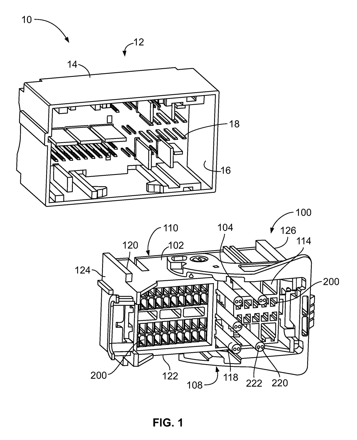
[0021]FIG. 1 is a perspective view of an electrical connector system 10 formed in accordance with an exemplary embodiment. The electrical connector system 10 includes a header connector 12, which may be mounted to a circuit board, and a connector assembly 100 configured to be mated with the header connector 12. The header connector 12 includes a housing 14 defining a cavity 16. The header connector 12 includes a plurality of header contacts 18 held by the housing 14 and arranged within the cavity 16 for electrical connection to the connector assembly 100. In the illustrated embodiment, the header contacts 18 are male contacts, such as pin contacts, blade contacts, and the like; however, other types of contacts may be provided in alternative embodiments. The connector assembly 100 is configured to be loaded into the cavity 16 to electrically connect to the header contacts 18. In an exemplary embodiment, the connector assembly 100 includes cables or wires extending therefrom configured t


PUM


Abstract

A connector assembly includes a housing having housing cavities extending between a mating end and a loading end. The housing having module latches associated with corresponding housing cavities. Contact modules are received in corresponding housing cavities. Each contact module having first and second module cavities extending between a front end and a rear end of the contact modules. The contact modules being held within the housing cavity by the corresponding module latch. Each contact module having an unshielded twisted pair (UTP) circuit, the UTP circuit includes first and second signal wires and first and second terminals terminated to the first and second signal wires. The signal wires being twisted along a length of the first and second signal wires.

Description


Claims


Application Information

Patent Timeline
Owner TYCO ELECTRONICS LOGISTICS AG (CH)
Why Eureka
Try Eureka