Terminal block and electronic appliance

a technology of terminal blocks and electronic appliances, applied in the direction of electrical equipment, connection, coupling device connection, etc., can solve the problems of increasing the risk of the force applied via a tool to the connecting screw being transmitted via the holding member to the board, the risk of the soldered portion and the risk of the soldered portion being separated or the production of cracks in the soldered portion

Active Publication Date: 2017-08-29
TDK CORPARATION
View PDF16 Cites 5 Cited by
  • Summary
  • Abstract
  • Description
  • Claims
  • Application Information

AI Technical Summary

Benefits of technology

The invention relates to a terminal block for electronic devices that prevents damage from forces acting perpendicularly towards its mounting surface. This design allows for better stability without tilting or other issues with the device's attachment to the circuit board.

Problems solved by technology

In this patented technical problem addressed in this patent text is how to attach multiple leads to a circuit board without damaging them during assembly.

Method used


Image

  • Terminal block and electronic appliance
  • Terminal block and electronic appliance
  • Terminal block and electronic appliance

Examples


Embodiment Construction

[0028]Preferred embodiments of a terminal block and a power supply apparatus will now be described with reference to the attached drawings.

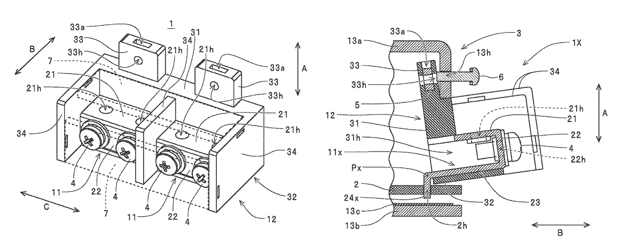
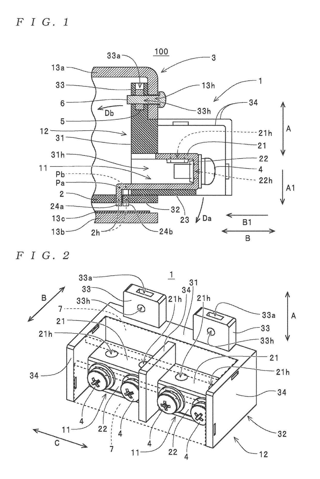
[0029]A power supply apparatus 100 depicted in FIG. 1 is one example of an “electronic appliance” according to the present invention and is configured by housing a circuit board 2, on which a terminal block 1 has been attached, inside a casing 3.

[0030]The circuit board 2 is one example of an “attached substrate” for the present invention. A conductive pattern, not illustrated, is formed on the circuit board 2, and the terminal block 1 and various electronic components, not illustrated, that construct a power supply circuit are mounted on (attached to) the circuit board 2. The casing 3 is one example of a “casing” for the present invention, includes an upper case 13a and a lower case 13b formed of metal plates, and is configured so as to house the circuit board 2 in a state where the terminal block 1 has been attached. Here, as described later, inser


PUM


Abstract

A terminal block includes: a terminal body with a screw hole for a screw used to connect a wire; and a terminal holder that holds the terminal body and has a substrate facing portion placed facing a first surface of a substrate. The terminal block is attached to the substrate by soldering the terminal body to a conductive pattern of the substrate with the substrate facing portion facing the first surface. The terminal holder has the substrate facing portion at one end in a first direction that becomes parallel to the thickness of the substrate when the terminal block is attached to the substrate. A casing fixing portion equipped with an insertion portion, into which a fastener for fixing the terminal holder to a casing that houses the substrate is inserted, is provided at another end in the first direction of the terminal holder.

Description


Claims


Application Information

Patent Timeline
Owner TDK CORPARATION
Why Eureka
Try Eureka