Magnetic memory configuration

A storage device, magnetic technology, applied in information storage, static memory, digital memory information and other directions, can solve the problems of data error, change of magnetization direction of hard magnetic layer, etc., to avoid the phenomenon of material transfer

Inactive Publication Date: 2008-04-02
INFINEON TECH AG
View PDF3 Cites 0 Cited by
  • Summary
  • Abstract
  • Description
  • Claims
  • Application Information

AI Technical Summary

Benefits of technology

This patented technology prevents electric migration caused when changing directions during printing while still allowing materials from moving freely within an inductor circuit board (MIC). By doing this it helps prevent damage or disconnection issues between different layers inside the MIC chip itself.

Problems solved by technology

This patented describes various technical featments related to magnesistance devices such as MRI machines. These improvements aim to improve performance without compromising any specific characteristics like speed and reliability over time.

Method used


Image

  • Magnetic memory configuration
  • Magnetic memory configuration
  • Magnetic memory configuration

Examples


Embodiment Construction

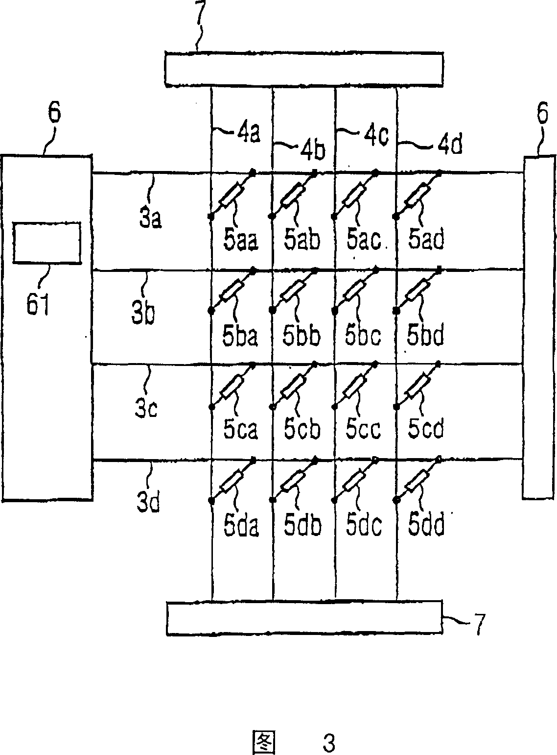
[0033] The magnetic storage device of FIG. 3 has 16 memory cells, 4 word lines, and 4 bit lines. In fact, the number of memory cells in the magnetic storage device is usually much larger than this, for example, it may have up to tens of thousands of memory cells. A magnetic storage device does not have to have the same number of word lines as the number of bit lines.

[0034] Reference numerals (3a to 3d) all represent word lines, and reference numerals (4a to 4d) represent bit lines. There is a memory cell (5aa to 5dd) at the intersection of each word line and each bit line. The current required by the word line is supplied by the first power supply device (6), and the current required by the bit line is supplied by the second power supply device (7).

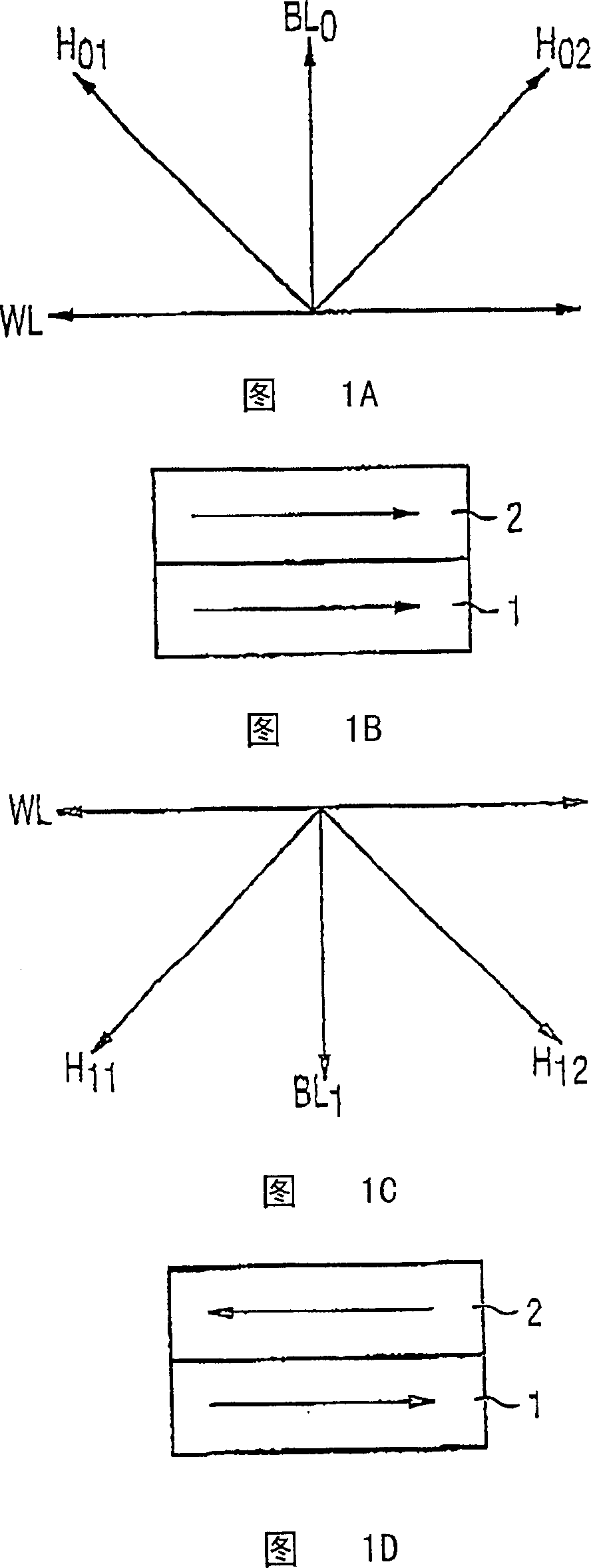
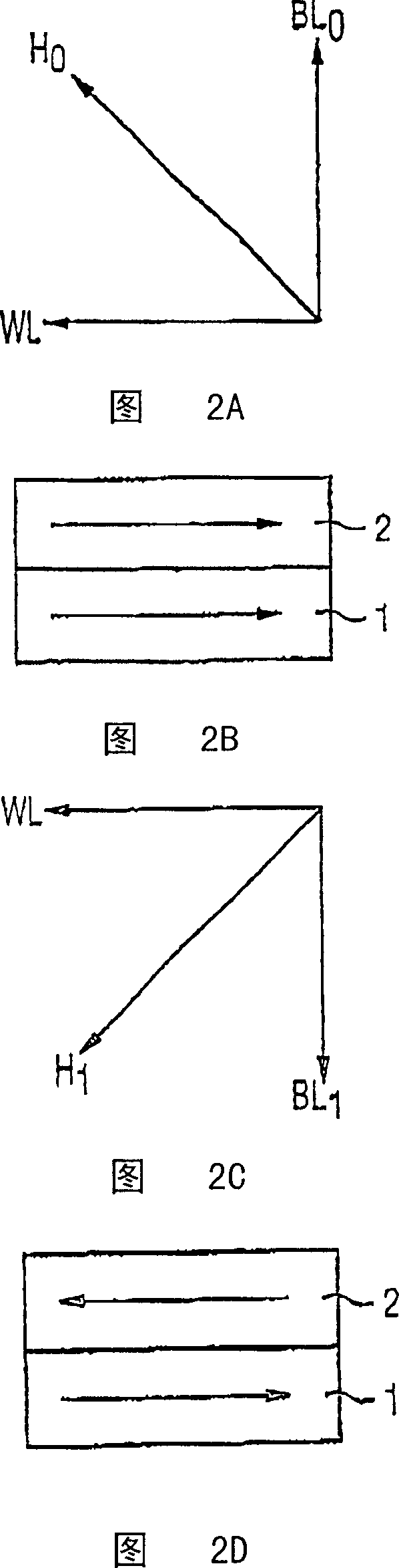
[0035] The process of writing data into a specially selected memory cell (such as 5ba) is that a current flows through the word line (3b) at first, and this current will generate a specific magnetic field, and then a current al


PUM


Abstract

The invention relates to a magnetic memory arrangement for saving data, which can be used to prevent the effects of ageing. Said memory arrangement comprises a cell field consisting of magnetic memory cells (5aa, ..., 5dd), which are arranged in a first direction and a second direction that is perpendicular to the first, a large number of electric lines in the first direction, a large number of electric lines in the second direction, whereby the magnetic memory cells (5aa, ..., 5dd) are arranged at each intersection of the electric lines (3, 4) in the first and second directions, a first power supply device (6) for respectively supplying selected electric lines with power in the first direction, a second power supply device (7) for respectively supplying selected electric lines with power in the second direction, whereby the second power supply device (7) is designed to set the direction of said power according to information that is to be written to the memory and the first power supply device (6) is designed to arbitrarily switch the direction of the power.

Description


Claims


Application Information

Patent Timeline
Owner INFINEON TECH AG
Why Eureka
Try Eureka