Spin current magnetization rotational element, magnetoresistance effect element, and magnetic memory

a technology of rotational elements and spin current magnets, applied in the field of spin current magnetization rotational elements, magnetoresistance effect elements, magnetic memory, etc., can solve the problem of high power consumption

Active Publication Date: 2021-04-01
TDK CORPARATION
View PDF0 Cites 6 Cited by
  • Summary
  • Abstract
  • Description
  • Claims
  • Application Information

AI Technical Summary

Benefits of technology

The present invention provides a new type of magnetoresistive (MR) element with improved performance compared to existing ones. This element includes two layers - a fixed layer made up of iron or nickel-iron alloy and a nonmagnetic layer placed between them. When this element is used for storing data, its resistance changes depending on how much electricity flows through it. By doing this, the element can store more data than previous types of memories without losing their ability to change state.

Problems solved by technology

The technical problem addressed in this patent text relates to improving the performance of magnetoresistors (referred to as GMR elements) due to their ability to reduce reverse currents while maintaining their long operating life.

Method used


Image

  • Spin current magnetization rotational element, magnetoresistance effect element, and magnetic memory
  • Spin current magnetization rotational element, magnetoresistance effect element, and magnetic memory
  • Spin current magnetization rotational element, magnetoresistance effect element, and magnetic memory

Examples


Embodiment Construction

[0035]Hereinafter, the disclosure will be described in detail with reference to the accompanying drawings. Drawings used in the following description may illustrate a characteristic portion in an enlarged manner for easy understanding of characteristics of the disclosure for convenience, and dimensional ratios and the like of respective constituent elements may be different from actual dimensional ratios and the like. Materials, dimensions, and the like which are exemplified in the following description are illustrative only, and the disclosure is not limited thereto. The disclosure can be carried out by appropriately making modifications in a range that exhibits an effect of the disclosure. In elements of the disclosure, another layer may be provided in a range that exhibits the effect of the disclosure.

(Spin Current Magnetization Rotational Element)

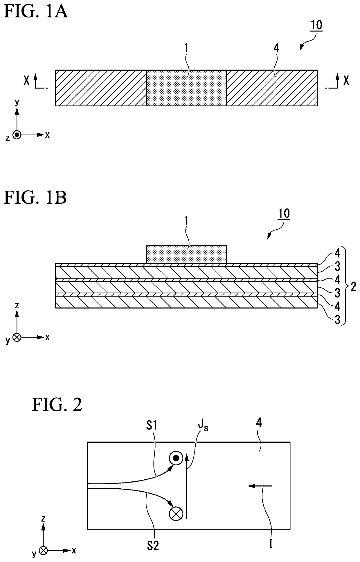
[0036]FIGS. 1A and 1B are schematic views illustrating an example of a spin current magnetization rotational element according to an embo


PUM


Abstract

Provided is a spin current magnetization rotational element, including: a first ferromagnetic metal layer for a magnetization direction to be changed; and a spin-orbit torque wiring which extends in a second direction intersecting a first direction that is a plane-orthogonal direction of the first ferromagnetic metal layer, the first ferromagnetic metal layer being located on one surface of the spin-orbit torque wiring, wherein the spin-orbit torque wiring has a structure in which a spin conduction layer and an interfacial spin generation layer are alternately laminated in the first direction, a number of a plurality of the interfacial spin generation layers is two or more, and at least one of the plurality of the interfacial spin generation layer is made of a compound.

Description


Claims


Application Information

Patent Timeline
Owner TDK CORPARATION
Why Eureka
Try Eureka