Traction engine

A tractor-integrated technology, which is applied in the field of tractors, can solve the problems of affecting the service life of the motor, the speed of the tractor is not stable, and the machine occupies a large area, and achieves the effect of small occupation area, simple structure and excellent performance

Inactive Publication Date: 2010-08-04
GUANGDONG UNIV OF TECH
View PDF7 Cites 0 Cited by
  • Summary
  • Abstract
  • Description
  • Claims
  • Application Information

AI Technical Summary

Problems solved by technology

[0002] The existing traction machine clamps the round rod (pipe) material by manually rotating the hand wheel to make the upper and lower pressure wheels press the traction rod (pipe) material. The clamping is time-consuming, laborious and inefficient; in addition, the The transmission system mostly adopts the chain transmission method, the speed of the t

Method used


Image

  • Traction engine
  • Traction engine
  • Traction engine

Examples


Embodiment

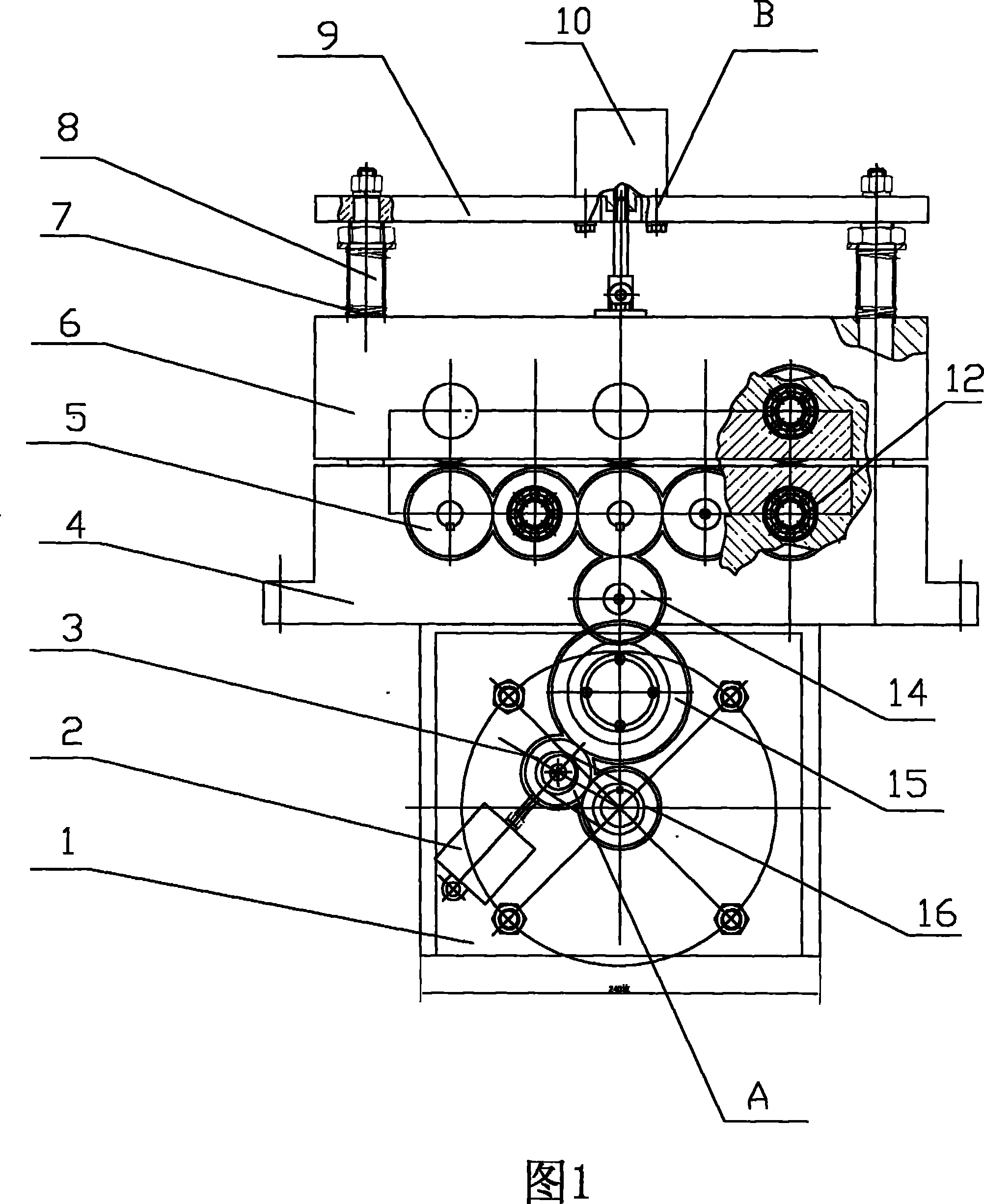
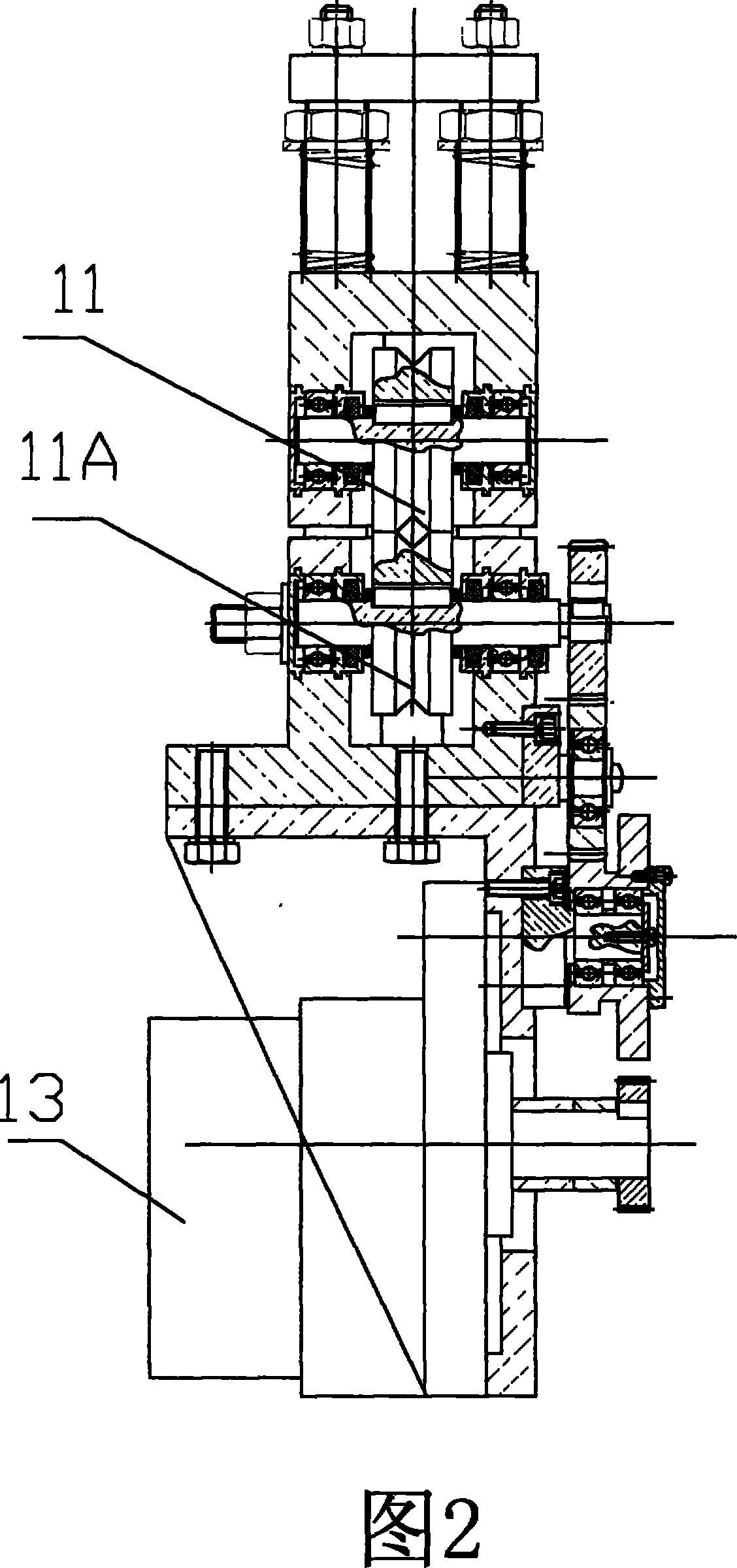
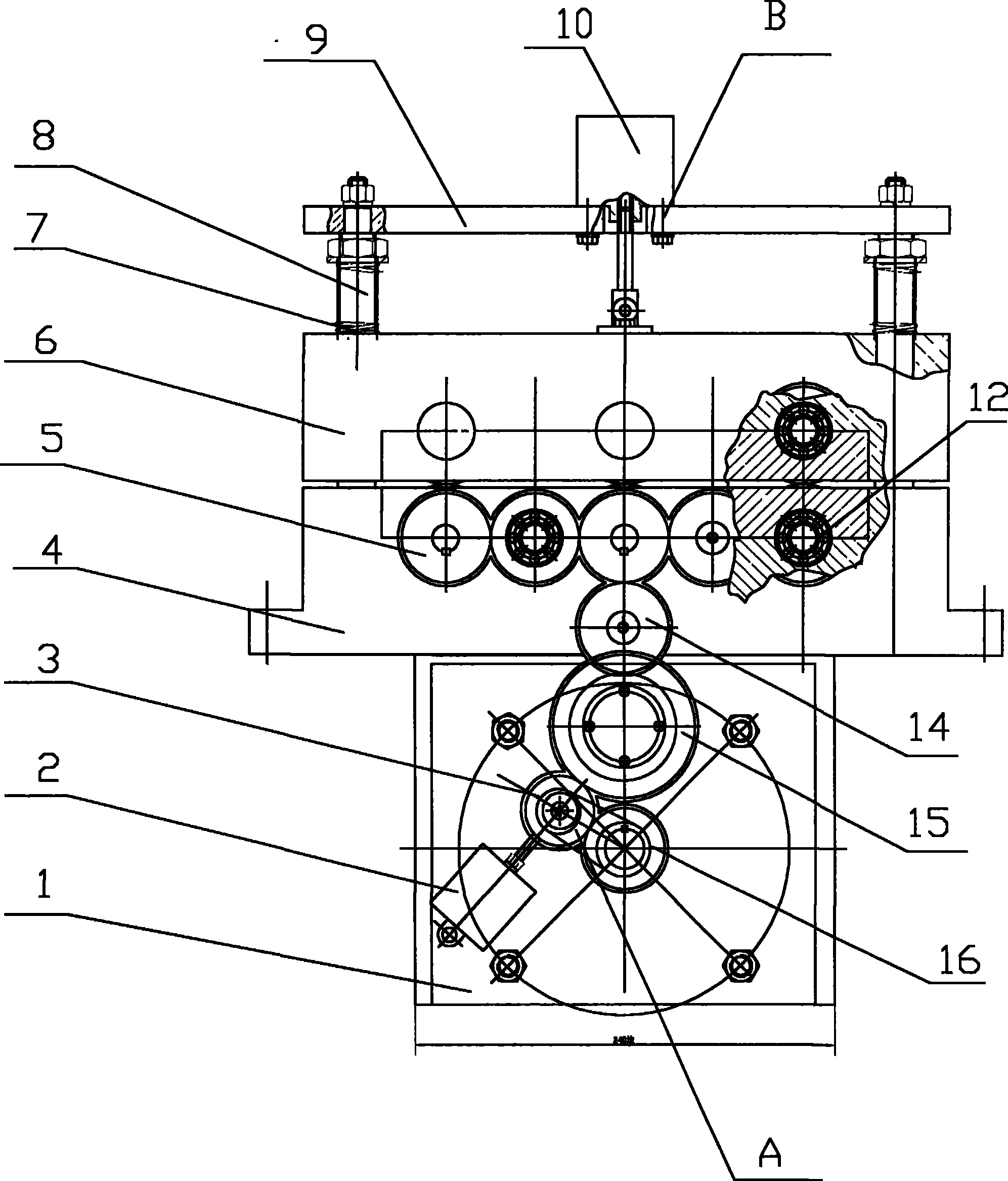
[0012] The structure diagram of the present invention is as figure 1 , 2 As shown, it includes a motor transmission frame 1, a fixed frame 4, an upper pressure wheel 11, a lower pressure wheel 11A, and a motor 13, wherein the motor 13 is installed on the motor transmission frame 1, and the lower pressure wheel 11A is installed on the fixed frame 4 , and the output shaft of the motor 13 is connected with the rotating shaft of the lower pressing wheel 11A through the transmission mechanism A, wherein the upper pressing wheel 11 is installed on the movable frame 6, and the movable frame 6 is connected with a lifting and pressing mechanism B.

[0013] In this embodiment, the lifting and pressing mechanism B connected to the movable frame 6 includes a spring 7, a guide column 8, a fixed plate 9, and a lifting piston cylinder 10, wherein the fixed plate 9 is sleeved with a compression spring 7 The guide column 8 is connected with the movable frame 6, the cylinder body of the lifting p


PUM


Abstract

The invention discloses a tractor for pulling round bar (pipe), which includes a motor transmission frame (1), a fixation frame (4), an upper press wheel (11), a lower press wheel (11A) and a motor (13). The motor (13) is installed on the motor transmission frame (1); the lower press wheel (11A) is installed on the fixation frame (4), output axel of the motor (13) is connected with rotary axel ofthe lower press wheel (11A) by the transmission mechanism (A); the upper press wheel (11) is mounted on a mobile frame (6) which connects with a lifting and pressing mechanism (B), the lifting and pressing mechanism (B) includes a spring (7), a guide column (8), a fixation plate (9) and a piston lifting cylinder (10), wherein the fixation plate (9) is connected with the mobile frame (6) by the guide column (8) equipped with the compression spring (7), the cylinder body of the piston lifting cylinder (10) is fixed on the fixation plate (9), and piston bar of the piston lifting cylinder (10) isconnected with the mobile frame (6). The tractor can fast and conveniently pull bar (pipe), can realize pulling motion with stable and non-shake line speed, and can make the pulled round bar (pipe) stop without turning off the motor.

Description


Claims


Application Information

Patent Timeline
Owner GUANGDONG UNIV OF TECH
Why Eureka
Try Eureka