Batten splicing structure
A wood sticking and bonding technology, which is applied in the direction of building construction, construction, window/door frame, etc., can solve the problems of low wood utilization rate and excessive waste, and achieve the effects of saving raw materials, high utilization rate, and reducing production costs
- Summary
- Abstract
- Description
- Claims
- Application Information
AI Technical Summary
Benefits of technology
Problems solved by technology
Method used
Image

Examples
Embodiment 1
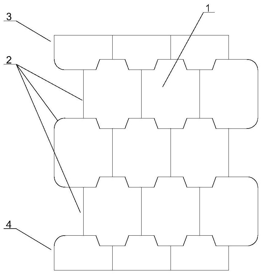
[0026] This embodiment provides a splicing structure of wood strips, such as Figure 1-2 As shown, it includes a plurality of above-mentioned wooden strip assemblies 2, and each wooden strip assembly 2 is staggered and interlocked and bonded to each other. Attachment one 3, the side that is arranged in the last wooden strip assembly 2 away from the bonding surface is bonded with attachment two 4 that match and engage with it. The one side of the attached plate 3 and the second attached plate 4 are all horizontal planes away from the bonding surface, and the first attached plate 3 and the second attached plate 4 can form a wooden strip assembly 2 .
[0027] In this embodiment, specifically, the wooden strip assembly 2 includes N wooden strip units 1, and N≥3, the wooden strip units 1 are columnar, each wooden strip unit 1 is arranged side by side, and each wooden strip unit 1 is bonded . Further, the cross section of the strip unit 1 is a rounded rectangle. The upper and lower
Embodiment 2
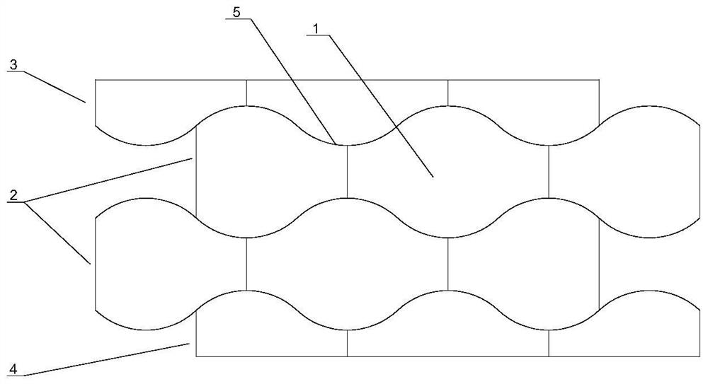
[0030] This embodiment provides a splicing structure of wood strips, such as Figure 3-4 As shown, it includes a plurality of above-mentioned wooden strip assemblies 2, and each wooden strip assembly 2 is staggered and interlocked and bonded to each other. Attachment one 3, the side that is arranged in the last wooden strip assembly 2 away from the bonding surface is bonded with attachment two 4 that match and engage with it. The one side of the attached board 3 and the second attached board 4 are both horizontal planes away from the bonding surface, and the first attached board 3 and the second attached board 4 can form a above-mentioned wooden strip assembly 2 .
[0031] In this embodiment, specifically, the wooden strip assembly 2 includes N wooden strip units 1, and N≥3, the wooden strip units 1 are columnar, each wooden strip unit 1 is arranged side by side, and each wooden strip unit 1 is bonded . Further, the cross-section of the strip unit 1 is rectangular, and arc-shap
PUM
 Abstract
Description
Claims
Application Information
 - R&D Engineer
- R&D Manager
- IP Professional
- Industry Leading Data Capabilities
- Powerful AI technology
- Patent DNA Extraction
Browse by: Latest US Patents, China's latest patents, Technical Efficacy Thesaurus, Application Domain, Technology Topic.
© 2024 PatSnap. All rights reserved.Legal|Privacy policy|Modern Slavery Act Transparency Statement|Sitemap