Remote instruction system, remote instruction method, and program product therefor

A technology of remote instructions and application programs, applied in closed-circuit television systems, components of television systems, editing/combining graphics or text, etc., can solve the problem that it is difficult to form a variety of annotation images, it is impossible to form and send annotation images, etc. question

Active Publication Date: 2007-11-14
FUJIFILM BUSINESS INNOVATION CORP
View PDF1 Cites 1 Cited by
  • Summary
  • Abstract
  • Description
  • Claims
  • Application Information

AI Technical Summary

Problems solved by technology

[0003] However, conventionally, in order to project an annotation image onto a real object according to an instruction given by a remote terminal of the above-mentioned remote pointing system, it is necessary to draw an annotation image using a dedicated drawing function prepared in advance at a remote location
For this rea

Method used


Image

  • Remote instruction system, remote instruction method, and program product therefor
  • Remote instruction system, remote instruction method, and program product therefor
  • Remote instruction system, remote instruction method, and program product therefor

Examples


Embodiment Construction

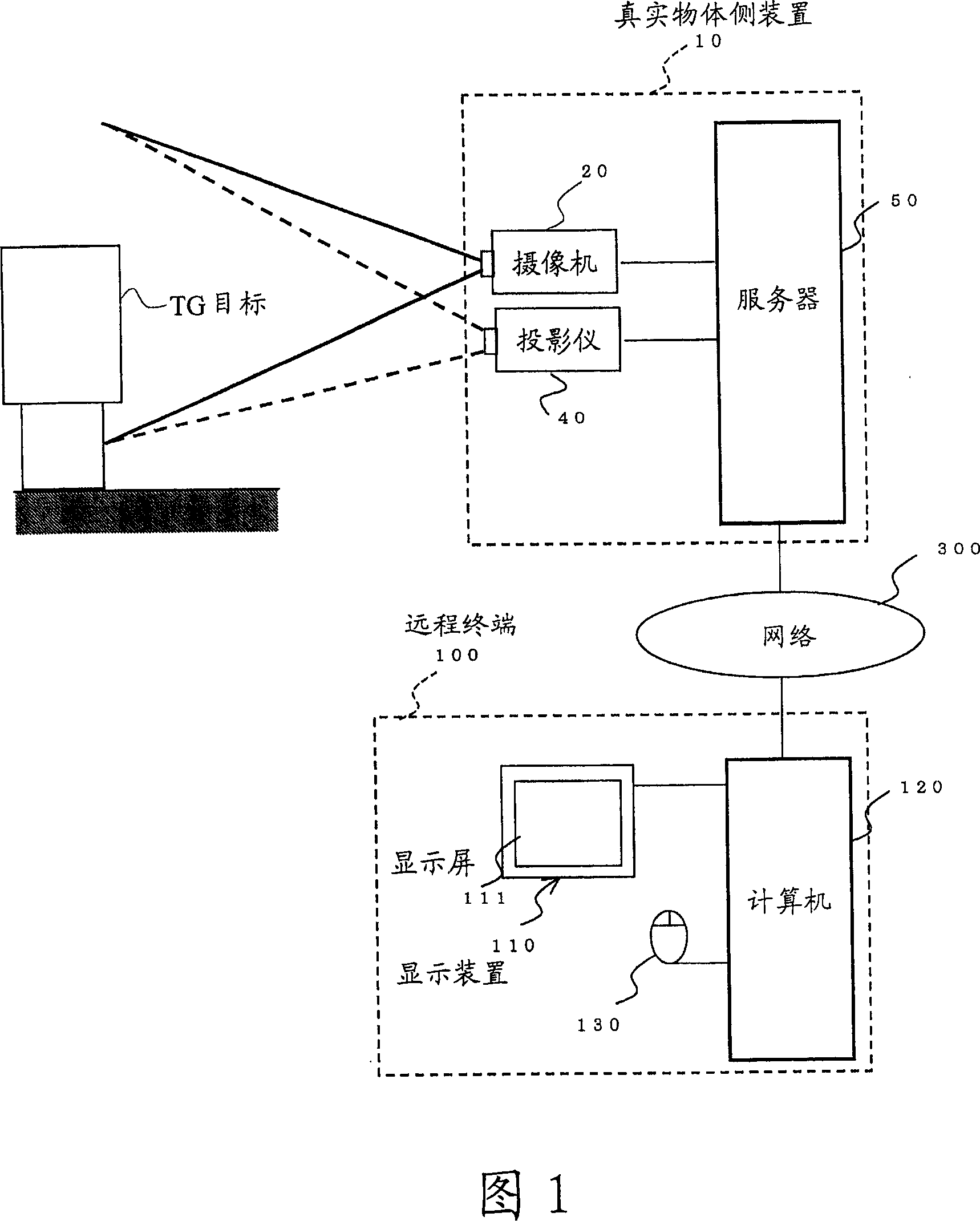
[0025] The embodiments of the present invention will be described below with reference to the drawings. Fig. 1 is a configuration diagram of a remote indication system according to an aspect of the present invention. The indicating system is provided with a real object side device 10, a remote terminal 100, and the like. The real object side device 10 and the remote terminal 100 are connected so that they can communicate with each other. Here, in FIG. 1, only one remote terminal 100 is shown, but a plurality of remote terminals 100 may also be connected to the real object side device 10 through the network 300.

[0026] The real object side device 10 is provided with a camera 20 serving as an image capturing section, a projector 40 serving as a projection section, a server 50 serving as a controller, and the like.

[0027] The camera 20 is composed of, for example, a CCD camera or the like, and is placed so that it can photograph the target TG. The image thus captured is loaded into


PUM


Abstract

A remote instruction system comprising an annotation forming portion that: overlay-displays an image of a target taken by an image taking portion, in a display area of application software; displays an edited image in the display area by use of the application software; extracts the edited image displayed according to a difference between displayed images prior to and subsequent to a generation of the edited image; and forms an annotation image from the edited image extracted to project the annotation image onto an image-taken area of the image taking portion by a projecting portion according to an instruction given on the basis of a taken image.

Description


Claims


Application Information

Patent Timeline
Owner FUJIFILM BUSINESS INNOVATION CORP
Why Eureka
Try Eureka