Device for changing displacement of slide vane compressor

A compressor and variable displacement technology, applied in the direction of rotary piston machinery, mechanical equipment, machine/engine, etc., can solve the problems of wear energy loss, compressor service life and mechanical efficiency reduction, etc., to reduce friction and wear, Effects of improving service life and mechanical efficiency and reducing exhaust volume

Inactive Publication Date: 2008-01-02
WUYI UNIV
View PDF0 Cites 5 Cited by
  • Summary
  • Abstract
  • Description
  • Claims
  • Application Information

AI Technical Summary

Benefits of technology

This patented technology uses an openings for inserting cards or parts inside it's mechanism. It also includes various features like cushion bushes, return springs, and strollers. These feature enhances performance without adding extra weight compared to traditional designs while maintaining their effectiveness over long periods of use.

Problems solved by technology

This patented technical problem addressed in this patents relates to improving the performance and lifespan of vane type compressors due to their compact design and low mass compared to other types of machines. Gas bypassing and sucking throttled techniques were developed but they also resulted in increased friction at each part leading to reduced machine durability overall.

Method used


Image

  • Device for changing displacement of slide vane compressor

Examples


Embodiment Construction

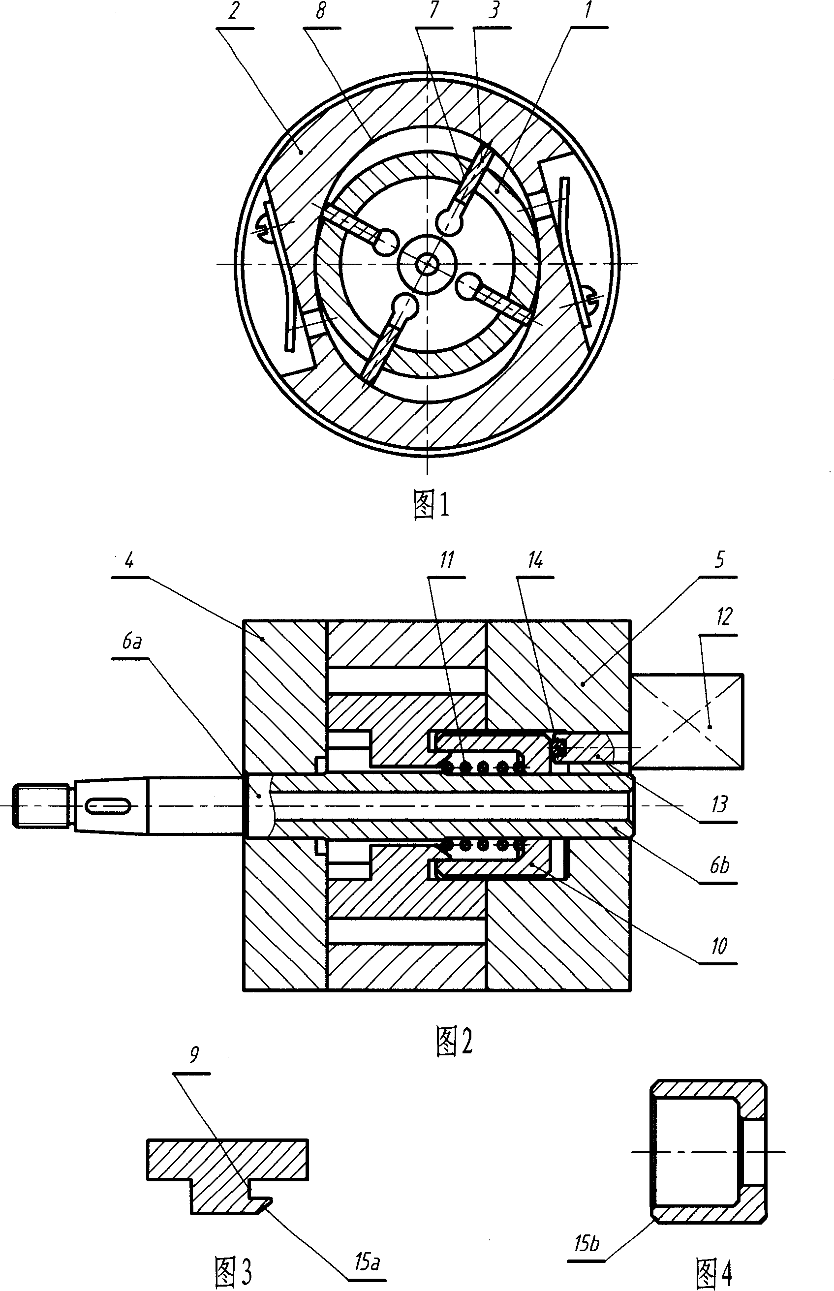
[0010] Fig. 1 and Fig. 2 respectively show a structural cross-sectional schematic diagram and a schematic working principle schematic diagram of a variable displacement device of a compressor according to the present invention. This embodiment adopts the structural scheme of double working chambers. The compressor includes a rotor 1, a cylinder body 2, a sliding vane 3, a front end cover 4 and a rear end cover 5; the two ends of the rotor 1 are made into journals 6a and 6b, respectively supported on On the front end cover 4 and the rear end cover 5, the front end cover 4 and the rear end cover 5 are directly or indirectly fixedly connected to the cylinder body 2; a chute 7 is provided along the radial direction of the rotor 1, more generally, The chute 7 is offset along the direction parallel to the axis of the rotor 1 (not shown in the figure); the flat sliding piece 3 is fitted in the chute 7 and slidably fit with it, the sliding piece 3 and the The quantity of the chute 7 is f


PUM


Abstract

The invention discloses a slide vane compressor variable-displacement device, which is characterized by the following: comprising rotor, cylinder, wiper and end lid; arranging the rotor in the cylinder; supporting the two ends of the rotor on the end lid of the cylinder two sides; opening several flat chute on the rotor; arranging the wiper in the chutes; sliding and fitting; opening card tank at the root of partly wiper; corresponding with the card tank; arranging a cutting sleeve; arranging the cutting sleeve on the axle neck of the rotor; proceeding axial move along the axial neck; arranging reset spring; arranging a stroke adjuster; generating position move; proceeding axial move through push bar to drive cutting sleeve; contacting the cutting sleeve with the wiper card tank; shrinking the wiper into the chute of the rotor; realizing various air displacement of the compressor.

Description


Claims


Application Information

Patent Timeline
Owner WUYI UNIV
Why Eureka
Try Eureka