Method for making micromachine moving piece and metal intraconnection thereof

An interconnection and micro-mechanical technology, which is applied in the field of integrating metal interconnection technology and micro-mechanical moving parts technology, can solve the problems of small resistance value and reduction of wires, etc.

Inactive Publication Date: 2008-09-03
TOUCH MICRO SYST TECH
View PDF3 Cites 0 Cited by
  • Summary
  • Abstract
  • Description
  • Claims
  • Application Information

AI Technical Summary

Problems solved by technology

Compared with semiconductor components, microelectromechanical components often need to be driven by a larger current, so the production of wires must meet the demand for high current, and must have a smaller resistance value. On the other hand, due to the m

Method used


Image

  • Method for making micromachine moving piece and metal intraconnection thereof
  • Method for making micromachine moving piece and metal intraconnection thereof
  • Method for making micromachine moving piece and metal intraconnection thereof

Examples


Embodiment Construction

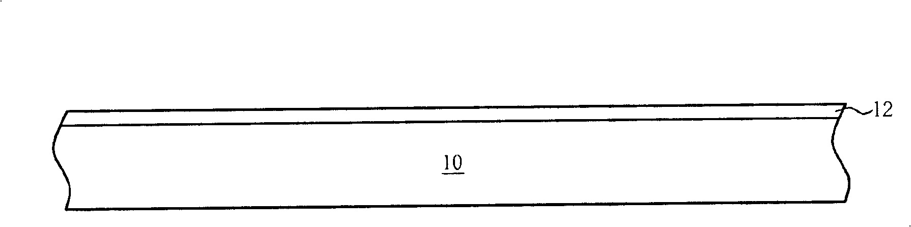
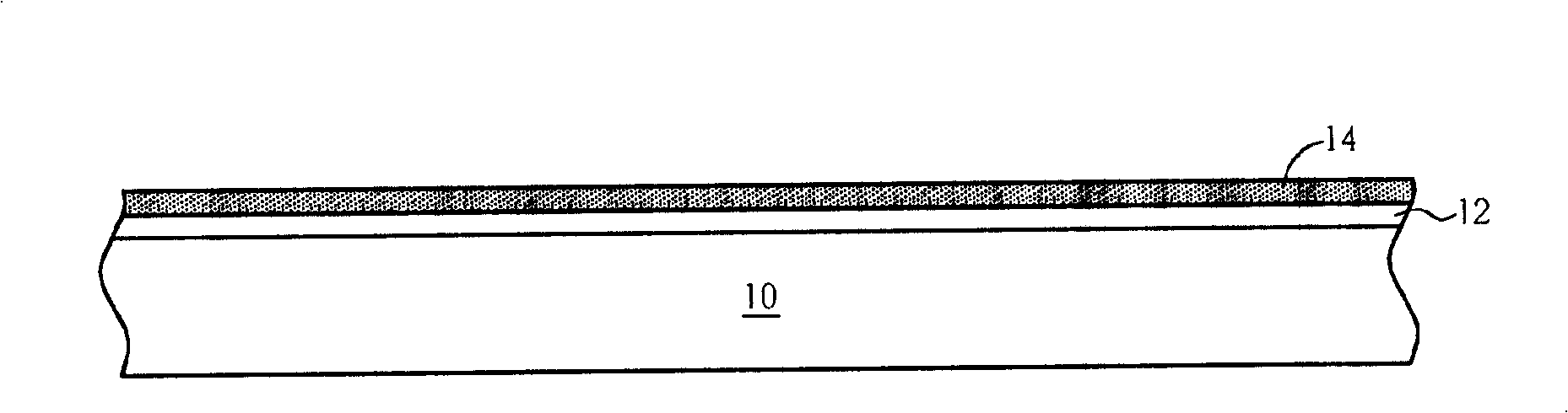
[0017] Please refer to Figure 1 to Figure 13 . Figure 1 to Figure 13 It is a schematic diagram of a method for manufacturing a micromechanical moving part and its metal interconnection in a preferred embodiment of the present invention. like figure 1 As shown, firstly, a substrate 10 is provided, such as a semiconductor wafer, wherein the substrate 10 may include electronic components (not shown) that have been fabricated and are to be subjected to a metal interconnection process. Next, a thermal oxide layer 12 is formed on the surface of the substrate 10 to serve as a stress buffer layer and a diffusion barrier layer for preventing subsequent metal interconnections from diffusing. In other embodiments of the present invention, the thermal oxide layer 12 may not be formed on the surface of the substrate 10 as required.

[0018] like figure 2 As shown, a seed layer 14 is subsequently formed on the surface of the thermal oxide layer 12 . The seed layer 14 can be formed by sp


PUM


Abstract

A method for producing a micromechanical moving part and metal interconnection lines thereof includes sequentially forming a first metal interconnection line pattern and a second metal interconnection line pattern stacked thereon on a substrate by a coating process at first; then forming an inner metal dielectric layer, and flattening the inner metal dielectric layer until the second metal interconnection line pattern is exposed; and at last fabricating at least one micromechanical moving part connected with the second metal interconnection line pattern on the inner metal dielectric layer by coating technique.

Description


Claims


Application Information

Patent Timeline
Owner TOUCH MICRO SYST TECH
Why Eureka
Try Eureka