Lift check valve

A check valve, lifting type technology, applied in the direction of control valves, valve devices, functional valve types, etc., can solve the problems of high corrosion, short service life of valves, frequent replacement, etc., and achieve good corrosion resistance and sealing performance , long service life effect

Inactive Publication Date: 2009-02-18
江苏明江阀业有限公司
View PDF0 Cites 4 Cited by
  • Summary
  • Abstract
  • Description
  • Claims
  • Application Information

AI Technical Summary

Benefits of technology

This new design improves on existing designs by adding an antirust coating that prevents damage from certain substances like water or other liquids used for industrial processes such as chemicals or oil refining operations. It also includes a lifting mechanism made up of two parts - one part acts as a spring loaded piston and another part called a shuttle rod – where there connects it together through bearings. When the pressure inside this system increases beyond its normal level (called overpressure), the springs push back against each other causing them to move closer towards their original position. By doing these movements, the weight of the load changes accordingly. A sensor detecting any movement allows feedback control signals to activate the actuator to change the direction of motion. Overall, this technology makes sure things run smoothly without damaging equipment while still being effective at preventing contamination caused by harmful gases during production.

Problems solved by technology

In this patented technical problem addressed by the inventors described at least two types of commonly available valving devices: conventional casting iron valved ferrous plates (CFFs) that have linings made from materials like carbon steel), and partially lined valvess rubber tubes (PVT). These valves can cause leaks when they come into contact with strongly acidic liquids due to their low resistance against erosion caused by high pH values found within these environments. Additionally, traditional methods involving stopping fluid supply during maintenance work may also lead to issues where there could be an accidental release of harmful substances if fluorine gas escapes through damaged parts of the CFO' s material.

Method used


Image

  • Lift check valve

Examples


Embodiment Construction

[0014] The lifting check valve of the present invention will be further described below in conjunction with the accompanying drawings.

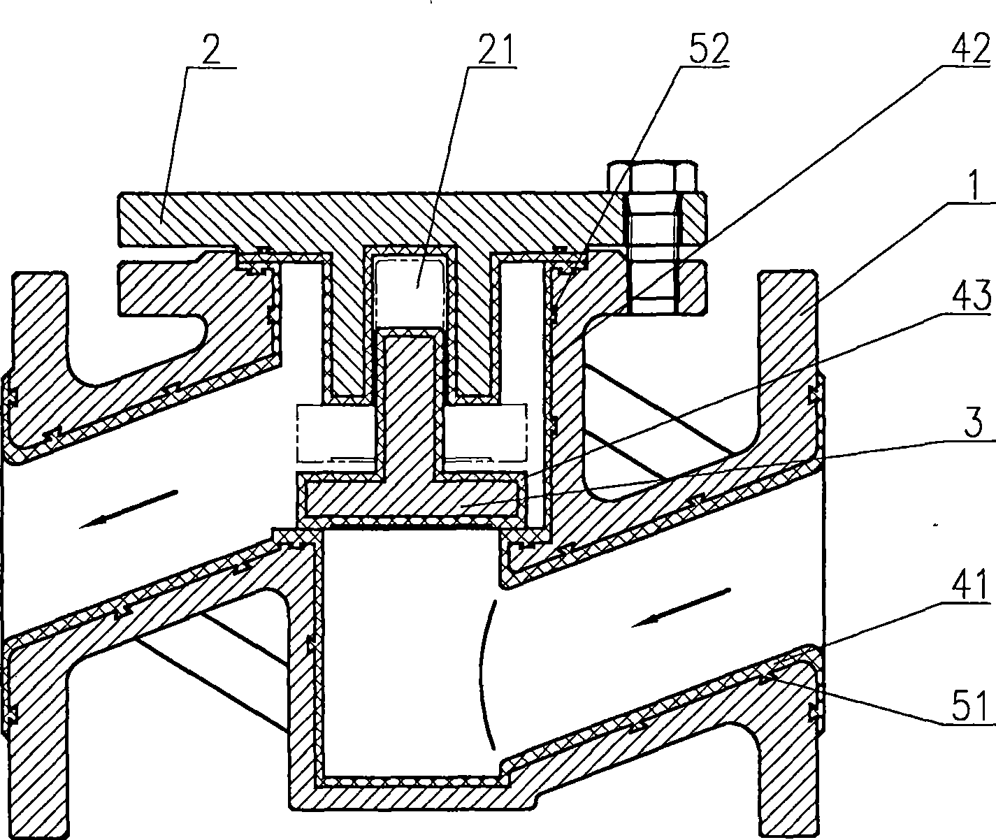
[0015] Such as figure 1 As shown, a lift check valve includes a valve body 1, a valve cover 2, and a valve flap 3. The difference is that the cross section of the valve flap 3 is an inverted "T" shape, and the valve cover 2 is provided with a guide groove 21. The top of the valve flap 3 is placed in the guide groove 21 and matched with the guide groove 21; the inner surface and the end surface of the valve body 1, the valve cover 2 are covered with anti-corrosion layers 41, 42, the valve flap The outer surface of 3 is covered with an anti-corrosion layer 43; the inner surface and end surface of the valve body 1, the valve cover 2 are provided with grooves 51, 52, and the anti-corrosion layer 41, 42 penetrates into the grooves 51, 52, respectively; The width of the notch of the grooves 51, 52 is not greater than the width of the groove bottom; the ab


PUM


Abstract

The invention discloses a lifting check valve which comprises a valve body, a valve cover, a valve flap and is characterized in that the section of the valve flap is inverted T-shaped; a guide groove is arranged on the valve cover; the top part of the valve flap is arranged in the guide groove and matched with the guide groove; the check valve has the advantages of good seal performance, erosion resistance, safety, reliability, long service life and being adjusted according the flow rate of the medium real-timely.

Description


Claims


Application Information

Patent Timeline
Owner 江苏明江阀业有限公司
Why Eureka
Try Eureka