Detection circuit for detecting movements of a movable object

A technology for detecting circuits and moving objects, which is applied in the input/output of user/computer interaction, electrical digital data processing, and input/output process of data processing, etc. To achieve the effect of simple manufacturing and low cost

Inactive Publication Date: 2009-05-06
KONINKLIJKE PHILIPS ELECTRONICS NV
View PDF1 Cites 0 Cited by
  • Summary
  • Abstract
  • Description
  • Claims
  • Application Information

AI Technical Summary

Benefits of technology

The invented detecting circuits are less expensive than traditional methods but still work well with small parts that may be mistakenly assembled together.

Problems solved by technology

The technical problem addressed in this patented technology relates to improving upon existing devices that use multiple sensors or lenses to determine if there was motion within them due to gravity. These conventional methods have limitations such as requiring complicated structures made up of many parts making production difficult and expensive.

Method used


Image

  • Detection circuit for detecting movements of a movable object
  • Detection circuit for detecting movements of a movable object
  • Detection circuit for detecting movements of a movable object

Examples


Embodiment Construction

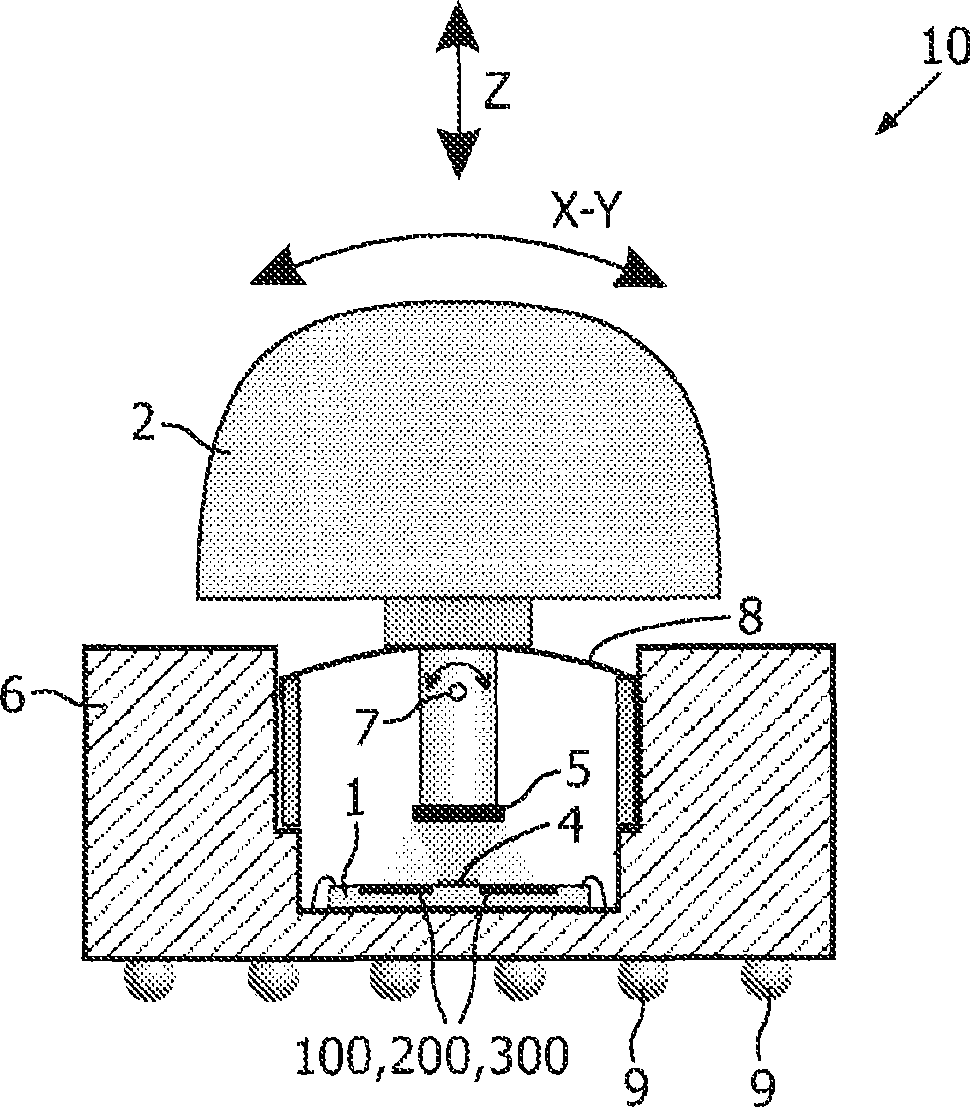
[0043] in cross section figure 1 The detection device 10 according to the present invention in includes the detection circuit 1 according to the present invention. The detection circuit 1 , such as an ASIC module, comprises detectors 100 , 200 , 300 , such as photodiodes, and a source 4 , such as a light source, such as any type of LED, located in a package 6 . A spring 8 is attached to the packaging 6 and the movable object 2 is coupled to the spring 8 . The movable object 2 includes a reflector 5 and a virtual rotation point 7 . The solder balls 9 of the package 6 allow the connection of the package 6 to the Figure 10 Device 20 in.figure 1 The x, y and z directions are also shown.

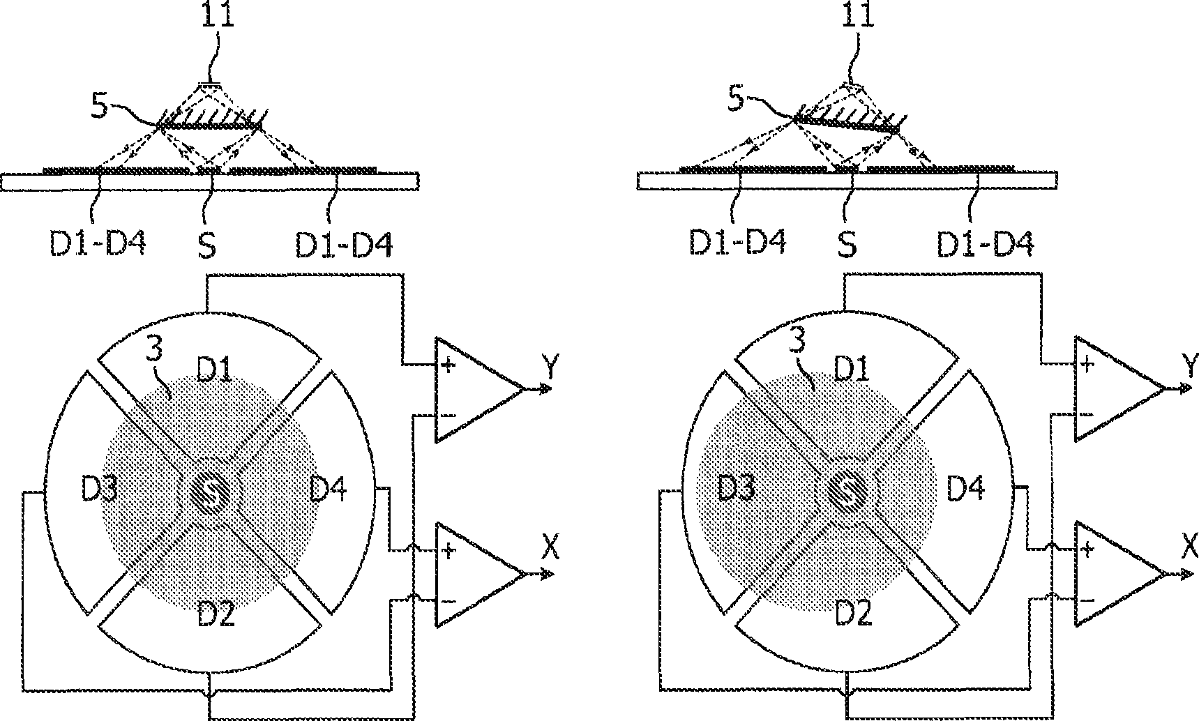
[0044] exist figure 2 The detection circuit 1 shown in a cross-sectional view for a non-moving movable object (left side) and a top view for a moved movable object (right side) is disclosed in a cross-sectional view to illustrate the detection circuit 1, detection The basic principle of the d


PUM


Abstract

Detection circuits (1) for detecting movements of movable objects (2) such as joysticks are provided with first detectors (100) for detecting first movements of the joysticks in first directions, comprising first detection units (101) for detecting a presence / absence of light spots (3), locations of the light spots (3) depending on said first movements, and with second detectors (200) for detecting second movements of the joysticks in second directions, comprising second detection units (201) for detecting first / second intensities of the light spots (3), intensities of the light spots (3) depending on said second movements. Such detection circuits (1) are less sensitive to misalignment of components during an assembly and simpler to produce and less costly. The second detectors (200) are entirely located within the light spot (3) independently from positions of the joysticks and the first and third detectors are partly located within the light spot (3) dependently on positions of the joysticks. The detection units (101) comprise photo diodes (120) and transistors (121) for digitizing the signals from the photo diodes (120).

Description


Claims


Application Information

Patent Timeline
Owner KONINKLIJKE PHILIPS ELECTRONICS NV
Why Eureka
Try Eureka