Imaging apparatus and method
A detector and electromagnetic ray technology, applied in measuring devices, using light for diagnosis, sensors, etc., can solve the problems of high attenuation of megahertz frequency signals, and achieve the effect of low cost and great practical value
- Summary
- Abstract
- Description
- Claims
- Application Information
AI Technical Summary
Problems solved by technology
Method used
Image

Examples
no. 1 example
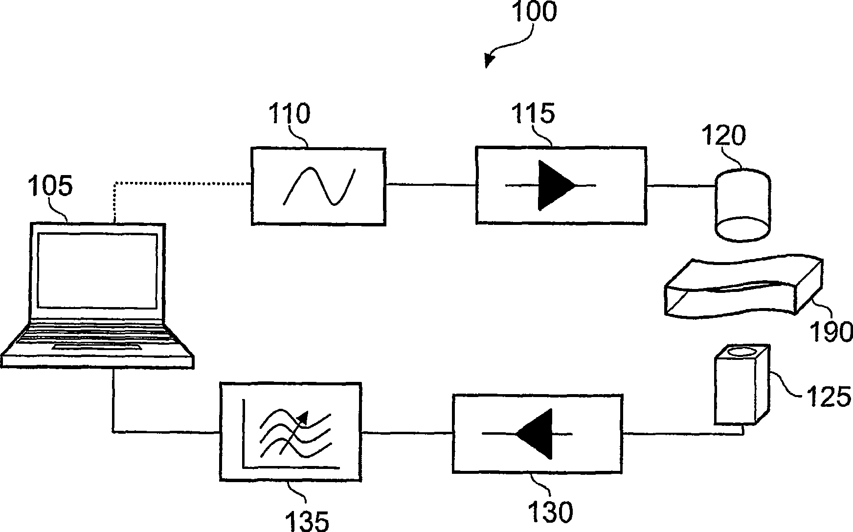
[0087] The radiation detector 125 is a solid state detector having a two-dimensional array of detector elements. According to a first embodiment, the detector element is a solid state diode.
[0088] Other detector elements may also be utilized. In some embodiments, the detector is a CMOS detector. In other embodiments, a CCD detector is used. In some embodiments of the invention, any suitable available infrared camera is employed.
[0089] Where a two-dimensional array of detector elements is used, a lens may be used to project an image of the sample onto the detector elements.
[0090] The detector 125 has a band-pass filter set to pass only rays having a wavelength of 900 nm to be incident on the diode array. Bandpass filters supporting other wavelengths may also be used.
[0091] Variable optical bandpass filters arranged to transmit wavelengths having different values or ranges of values may also be used. Diffraction gratings and tunable diffraction gratings can al
example 1
[0128] Figure 8 (a) shows a part of an object to be tested on paper with printed text. Two bags made of plastic material and containing a powdered substance are covered in paper. Figure 8 (b) shows the paper folded once in the process of stuffing the paper into the envelope. Figure 8 (c) shows the sealed envelope.
[0129] Figure 8 (d) is obtained using the device according to the first embodiment of the present invention Figure 8 (c) Imaging of the sample shown. Even though the paper is enclosed in a light-tight envelope, the characters on the paper are clearly visible in the imaging.
[0130] In a device according to an embodiment of the present invention, the resulting image is then processed using further image processing techniques such as Optical Character Recognition (OCR) in order to add text to the database.
[0131] Embodiments of the present invention find a wide variety of applications related to the safety of people and property. For example, embodiments
example 2
[0136] Figure 9 (a) shows a tooth before imaging with the apparatus according to the first embodiment of the present invention. Figure 9 (b) shown with Figure 9 (a) Photograph of the same viewing direction, locked-in near-infrared (NIR) imaging of the same sample. Figure 9 (c) shows the corresponding Figure 9 (b) Generated fingerprint map.
[0137] Region A with higher contrast compared to the surrounding part of the tooth is evident in the NIR imaging. This region corresponds to a lower difference between the amplitudes of the reference signal and the detector signal. This indicates that region A corresponds to a region of lower density. It can also be seen that the boundary B between the enamel and dentin of the tooth is displayed in a relatively dark color. Boundary regions are also considered to be regions with relatively low density.
[0138] Figure 9 (d) is to show Figure 9 Photograph of the cut surface of the tooth in (a). It can be seen that there is a ca
PUM
| Property | Measurement | Unit |
|---|---|---|
| Wavelength | aaaaa | aaaaa |
| Wavelength | aaaaa | aaaaa |
Abstract
Description
Claims
Application Information
 - R&D Engineer
- R&D Manager
- IP Professional
- Industry Leading Data Capabilities
- Powerful AI technology
- Patent DNA Extraction
Browse by: Latest US Patents, China's latest patents, Technical Efficacy Thesaurus, Application Domain, Technology Topic.
© 2024 PatSnap. All rights reserved.Legal|Privacy policy|Modern Slavery Act Transparency Statement|Sitemap