Ink-feeding cartridge containing element for cutting-off ink

A technology of ink supply and assembly, applied in printing and other directions, can solve problems such as ink leakage, and achieve the effect of preventing ink leakage

Inactive Publication Date: 2009-08-05
MICROJET TECH
View PDF0 Cites 0 Cited by
  • Summary
  • Abstract
  • Description
  • Claims
  • Application Information

AI Technical Summary

Benefits of technology

The technical feature described in this patented technology relates to improving printing quality while reducing waste caused by excessive bleeding during periods where no inking supplies are being used for printing without having them stopped working properly due to lack of maintenance. This results in improved efficiency and reduced costs associated therewith.

Problems solved by technology

This technical problem addressed in this patents relates to improving the reliability of continuously supplying inks during printing without causing any issues such as ink waste due to frequent replacement operations.

Method used


Image

  • Ink-feeding cartridge containing element for cutting-off ink
  • Ink-feeding cartridge containing element for cutting-off ink
  • Ink-feeding cartridge containing element for cutting-off ink

Examples


Embodiment Construction

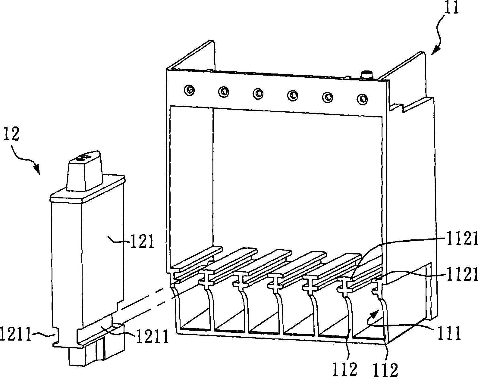
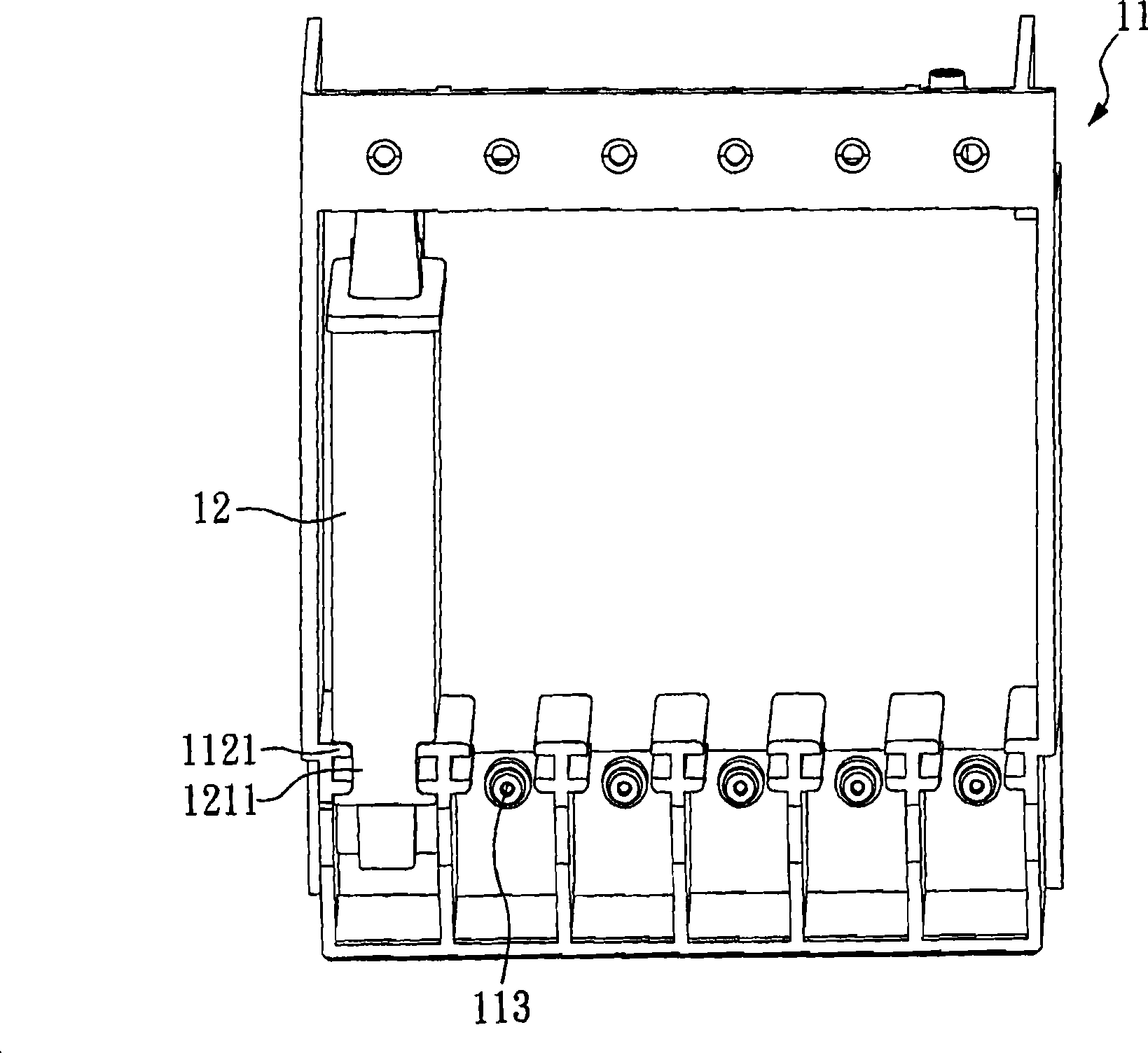
[0034] Such as Figure 4 As shown, this is a schematic diagram of a continuous ink supply system according to a preferred embodiment of the present invention. The continuous ink supply system of the present invention includes an ink supply box carrier 21 and an ink supply box 22, wherein the ink supply box carrier 21 includes a plurality of ink supply box compartments 211, and the ink supply box 22 can be arranged here for supplying Ink cartridge compartment 211. In order to fix the ink supply box 22 on the ink supply box support frame 21, two grooves 2211 are included on the side of the ink supply box 22, and the partition wall 212 on the opposite side of the ink supply box compartment 211 also includes two protrusions. Edge 2121. Therefore, the ink supply cartridge 22 can be moved into or withdrawn from the ink supply cartridge compartment 211 of the ink supply cartridge carrier 21 through the mutual sliding of the groove 2211 and the flange 2121 . Moreover, due to the desig


PUM


Abstract

The invention relates to an ink supply casket comprising an ink stop component. The ink supply casket comprises a shell and the ink stop component, wherein the shell comprises a top post which is arranged on the shell, and extends to a side wall of the shell; and the side wall is provided with at least one insertion hole. Moreover, the ink stop component is arranged in the shell, and comprises a base, an elastic component and at least one guide post, wherein the elastic component and the at least one guide post are positioned on both sides of the base respectively, and at least one guide post is inserted in at least one corresponding insertion hole and protrudes out of the side wall of the shell.

Description


Claims


Application Information

Patent Timeline
Owner MICROJET TECH
Why Eureka
Try Eureka