Magnetic dividing device

The technology of an indexing device and indexing plate is applied in the directions of metal processing mechanical parts, precision positioning equipment, metal processing equipment, etc. simple structure

Inactive Publication Date: 2009-09-02
王建滨
View PDF0 Cites 4 Cited by
  • Summary
  • Abstract
  • Description
  • Claims
  • Application Information

AI Technical Summary

Benefits of technology

This technology uses magnetism or sensors on both its main body (the rotor) and its housing to detect changes caused by movement within it. It then generates signals that are used to calculate angles based on these movements. These calculations help computers accurately move objects around inside them without getting affected from vibrations such as winds or other environmental factors like rainwater.

Problems solved by technology

This technical problem addressed in this patented text relates to improving accuracy during machining processes such as turning and millings while ensuring accurate placement of the part being worked upon with an index mechanism attached at both ends (spindles). Current mechanisms have limitations due to complexity, expensive components, size constraints, difficulty in handling them, etc., making their use difficult without sacrifices precision.

Method used


Image

  • Magnetic dividing device
  • Magnetic dividing device
  • Magnetic dividing device

Examples


Embodiment 1

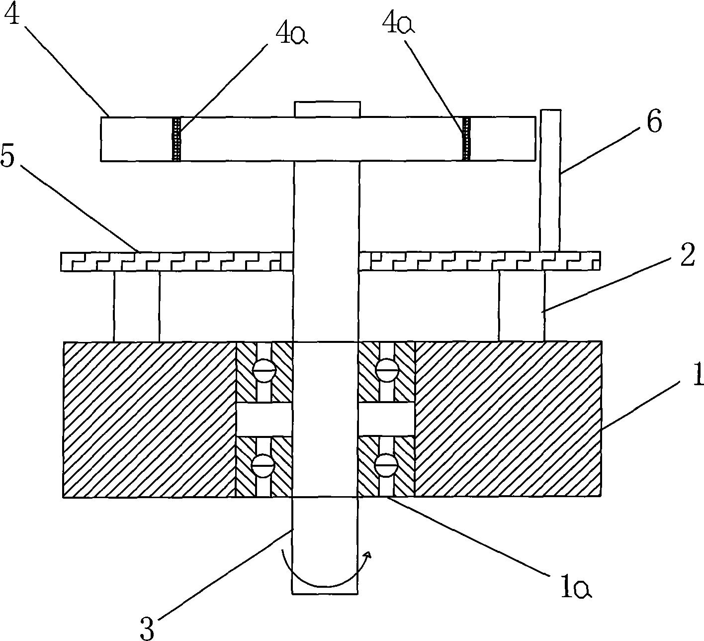
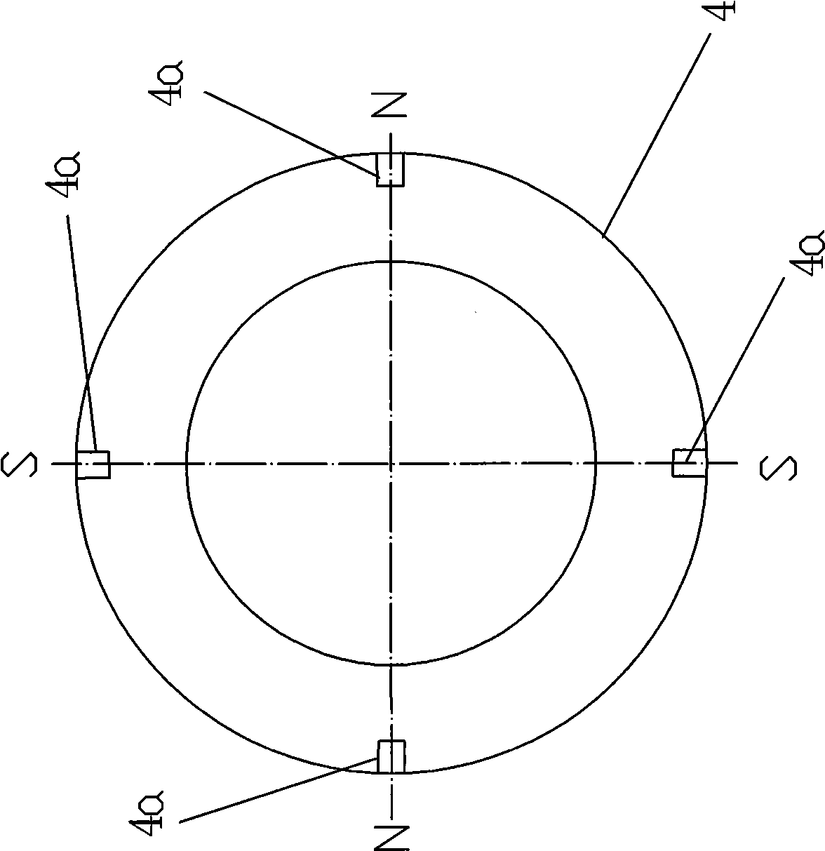
[0017] like figure 1 , figure 2 As shown, a magnetic indexing device includes a support 1, a support 2, a rotating shaft 3, a magnetic indexing plate 4, a circuit board 5 and an IC sensor 6, the support 1 is provided with a bearing 1a, and the rotating shaft 3 rotates through the bearing 1a Connected to the support 1, the support 2 is fixed on the support 1, the magnetic indexing plate 4 is fixed on one end of the rotating shaft 3, and the magnetic indexing plate 4 is evenly embedded with four magnetic steels 4a along the circumference of the circumference. The steel 4a divides the circumference of the magnetic indexing disk into 4 equal parts, and the angle between each two magnetic steels 4a is 90 degrees. The circuit board 5 is fixed on the bracket 2, the IC sensor 6 is fixed on the circuit board 5, the IC sensor 6 is located on one side of the outer edge of the magnetic indexing plate 4, and the IC sensor 6 is opposite to the magnetic steel 4a on the magnetic indexing plate

Embodiment 2

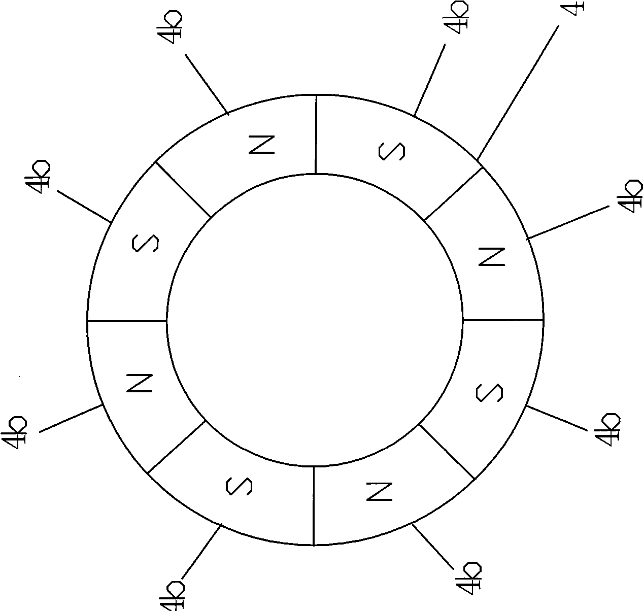
[0019] like figure 1 , image 3 As shown, a magnetic indexing device includes a support 1, a support 2, a rotating shaft 3, a magnetic indexing plate 4, a circuit board 5 and a Hall sensor 6, the support 1 is provided with a bearing 1a, and the rotating shaft 3 passes through the bearing 1a is rotatably connected to the support 1, the support 2 is fixed on the support 1, the magnetic indexing plate 4 is fixed on one end of the rotating shaft 3, and the magnetic indexing plate 4 is uniformly magnetized along the circumference to form 8 evenly distributed The permanent magnet poles 4b, the eight permanent magnet poles 4b divide the circumference of the magnetic indexing disk into 8 equal parts, and the angle between each two permanent magnet poles 4b is 45 degrees. The circuit board 5 is fixed on the bracket 2, the Hall sensor 6 is fixed on the circuit board 5, the Hall sensor 6 is located on one side of the outer edge of the magnetic indexing plate 4, and the Hall sensor 6 is on


PUM


Abstract

The invention relates to a magnetic dividing device which comprises a supporting seat, a bracket and a rotating shaft, wherein the rotating shaft is arranged on the supporting seat by a bearing, and the bracket is fixed on the supporting seat. The magnetic dividing device is characterized by also comprising a magnetic dividing disk, a circuit board and a magnetic sensor, wherein the magnetic dividing disk is fixed on one end of the rotating shaft, the circuit board is fixed on the bracket, and the magnetic sensor is fixed on the circuit board; magnetism is sequentially charged at the edge of the magnetic dividing disk according to the preset division to form a plurality of evenly distributed permanent-magnet poles, the magnetic sensor is positioned at one side of the outer edge of the magnetic dividing disk, and the magnetic sensor is opposite to the permanent-magnet poles of the magnetic dividing disk. The permanent-magnet poles on the magnetic dividing disk are also replaced by magnetic steel. The invention has simple structure, high precision and a certain shakeproof function.

Description


Claims


Application Information

Patent Timeline
Owner 王建滨
Why Eureka
Try Eureka