Profile plate used for heat exchanger and heat exchanger
A technology of heat exchangers and profiles, applied in evaporators/condensers, lighting and heating equipment, refrigeration components, etc., can solve problems such as changes in binding force, shedding of plates, and discoloration due to heat, so as to reduce the contact area and avoid The effect of plate falling off
- Summary
- Abstract
- Description
- Claims
- Application Information
AI Technical Summary
Problems solved by technology
Method used
Image


Examples
Example Embodiment
[0033] Example 1:
[0034] See Figure 4 , This figure is a perspective view of the appearance of the profile plate for the heat exchanger of the present invention.
[0035] Such as Figure 4 As shown, the surface of the profile plate in this embodiment has protruding ribs arranged along the length direction of the profile plate. In order to detail the specific structure of the profile plate, please refer to Figure 5 , The picture is Figure 4 B-B cross-sectional view.
[0036] Such as Figure 5 As shown, one side surface 21 of the profile plate is provided with first ribs 211, and there are at least two first ribs 211 parallel to each other. It is understandable that the number of the first ribs 211 can be set according to the width dimension of the profile plate. When the width dimension of the profile plate is larger, appropriate consideration should be given to increasing the number of the first ribs 211.
[0037] Another example Figure 5 As shown, the second rib 221 is provide
Example Embodiment
[0046] Example 2:
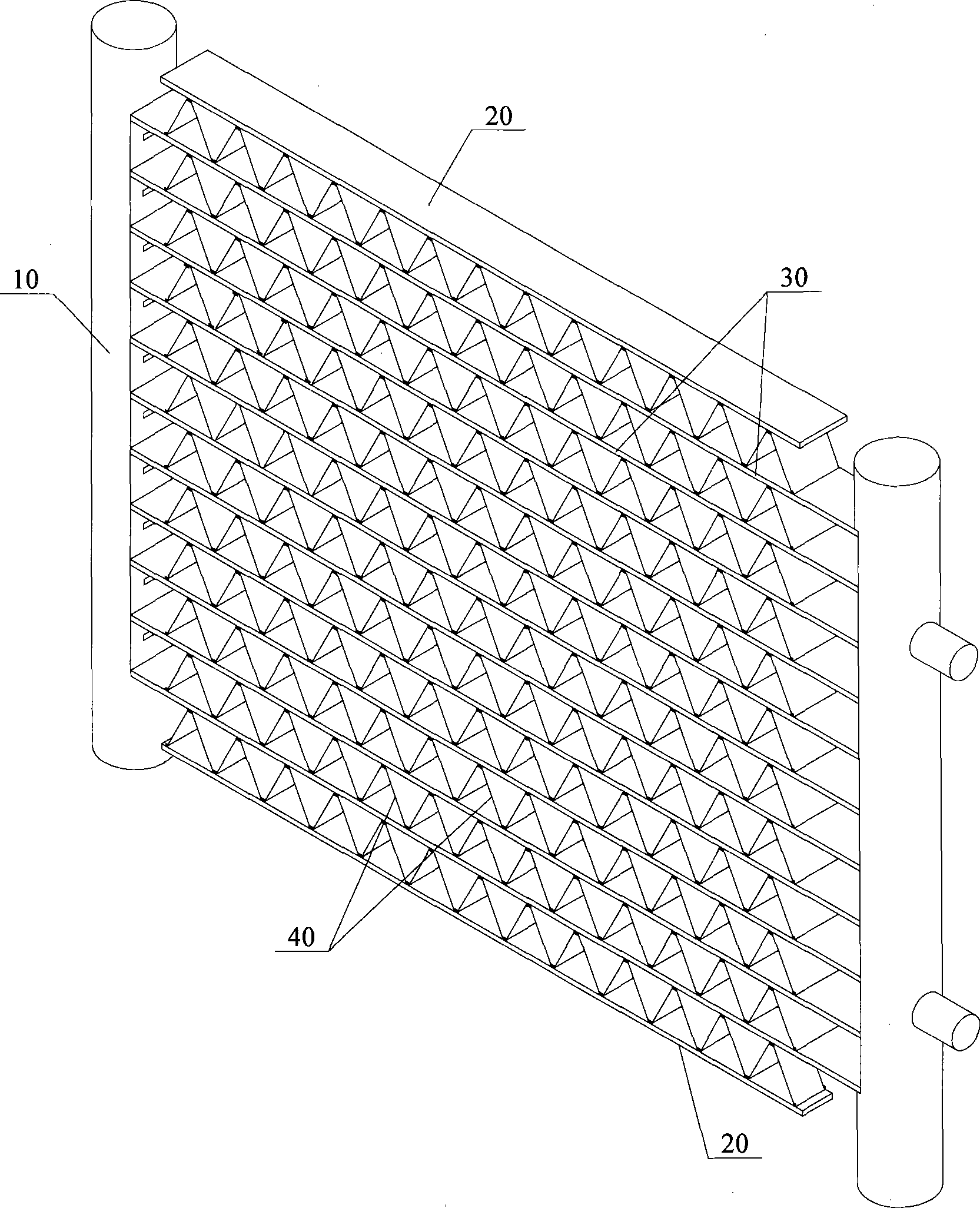
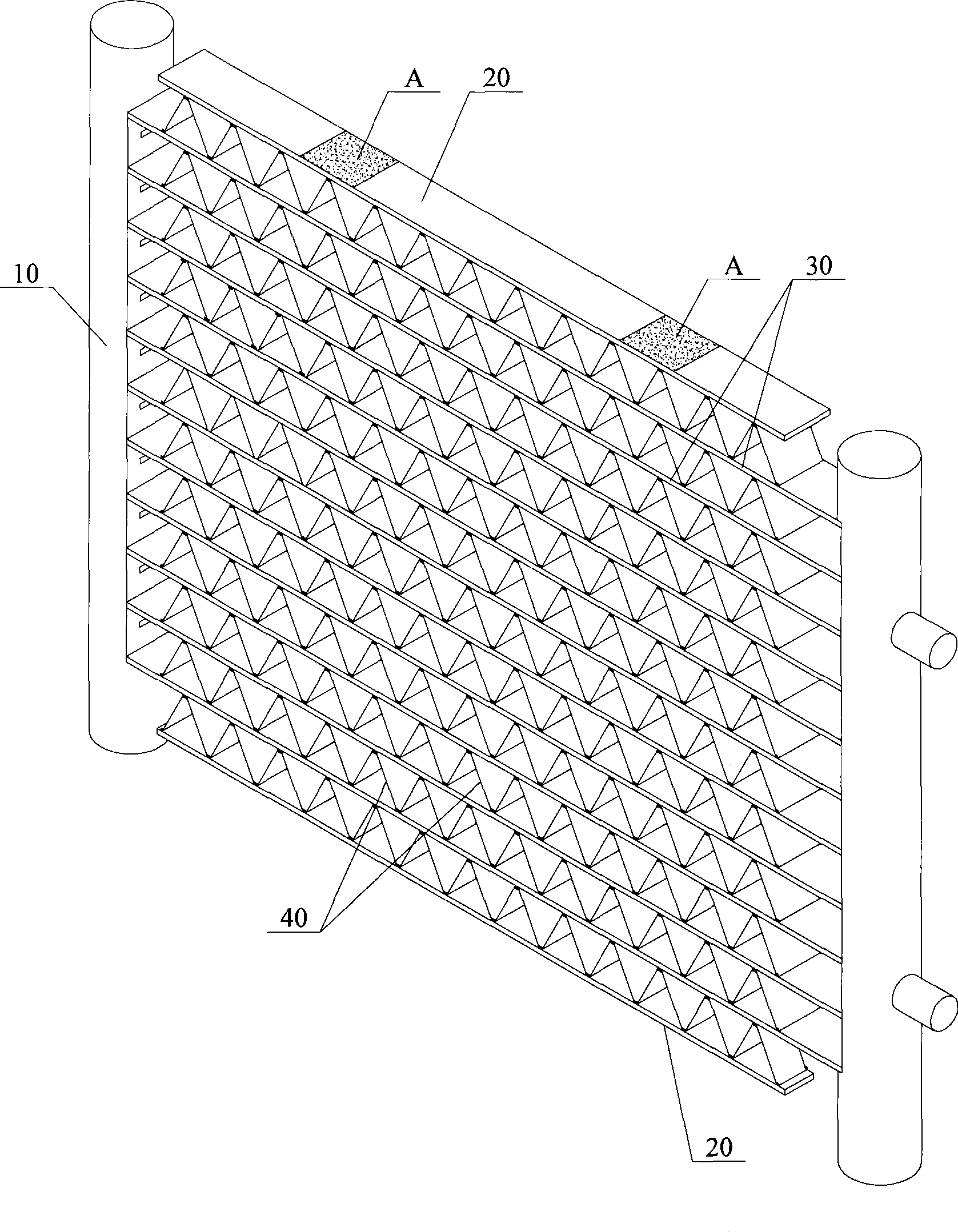
[0047] See Figure 7 , This figure is a schematic diagram of the overall structure of the heat exchanger of the present invention.
[0048] Such as Figure 7 As shown, compared with the existing heat exchanger, the heat exchanger 9 provided by the present invention has the same structure and connection relationship of the main components that complete the working cycle.
[0049] In the working cycle, the refrigerant enters the collecting pipe 1 from the inlet pipe 6, and the inner cavity (not shown in the figure) of the collecting pipe 1 is divided into upper and lower parts due to the partition (not shown in the figure). In two parts, the refrigerant flows along the small holes in the flat flow tube 3 from the liquid collection tube 1 at one end to the liquid collection tube 1 at the other end, and then flows back through the other flat flow tubes 3. The refrigerant is flowing At the same time, it exchanges heat with the air blown through the plates 4 between the
PUM
 Abstract
Description
Claims
Application Information
 - R&D Engineer
- R&D Manager
- IP Professional
- Industry Leading Data Capabilities
- Powerful AI technology
- Patent DNA Extraction
Browse by: Latest US Patents, China's latest patents, Technical Efficacy Thesaurus, Application Domain, Technology Topic.
© 2024 PatSnap. All rights reserved.Legal|Privacy policy|Modern Slavery Act Transparency Statement|Sitemap