Energy-saving air compressor

An air compressor and frame technology, applied in the field of compressors, can solve the problems of loud noise, complex structure, and power consumption, and achieve the effects of less noise, strong wind, and less force

Inactive Publication Date: 2009-10-28
刘文
View PDF0 Cites 0 Cited by
  • Summary
  • Abstract
  • Description
  • Claims
  • Application Information

AI Technical Summary

Benefits of technology

This new design allows for better efficiency by utilizing multiple components that move together instead of just one component being fixedly attached at once. It also includes an improved structure where there's no longer any unnecessary parts like motors or gears used during movement. Overall, this technology makes machines smarter without consuming too much power from their main battery source.

Problems solved by technology

The technical problem addressed by this patented technology is that current household compressed gas (CNG) systems require complicated mechanisms for compression, consuming energy or producing noise during operation due to their complexity structure.

Method used


Image

  • Energy-saving air compressor
  • Energy-saving air compressor

Examples


Embodiment Construction

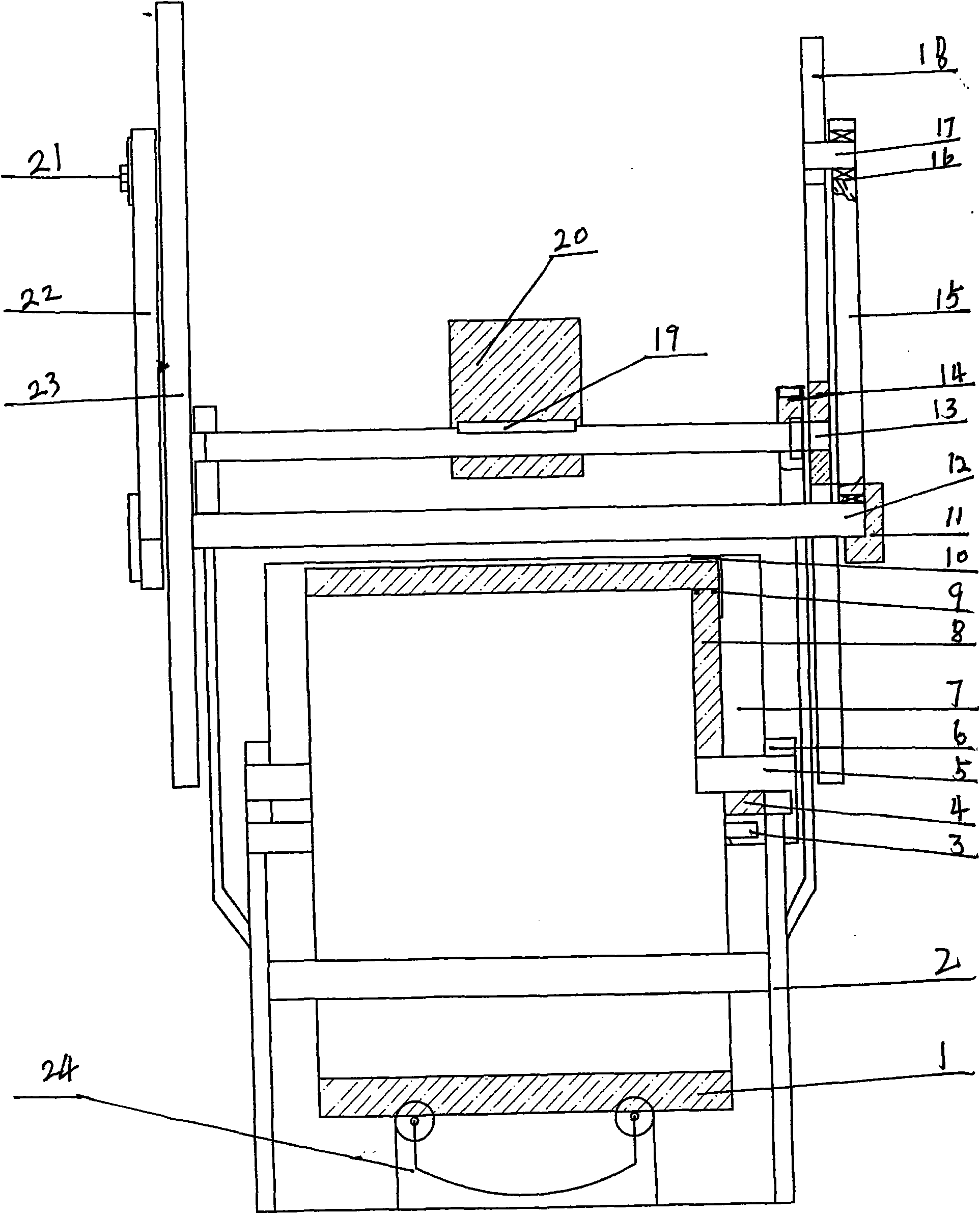
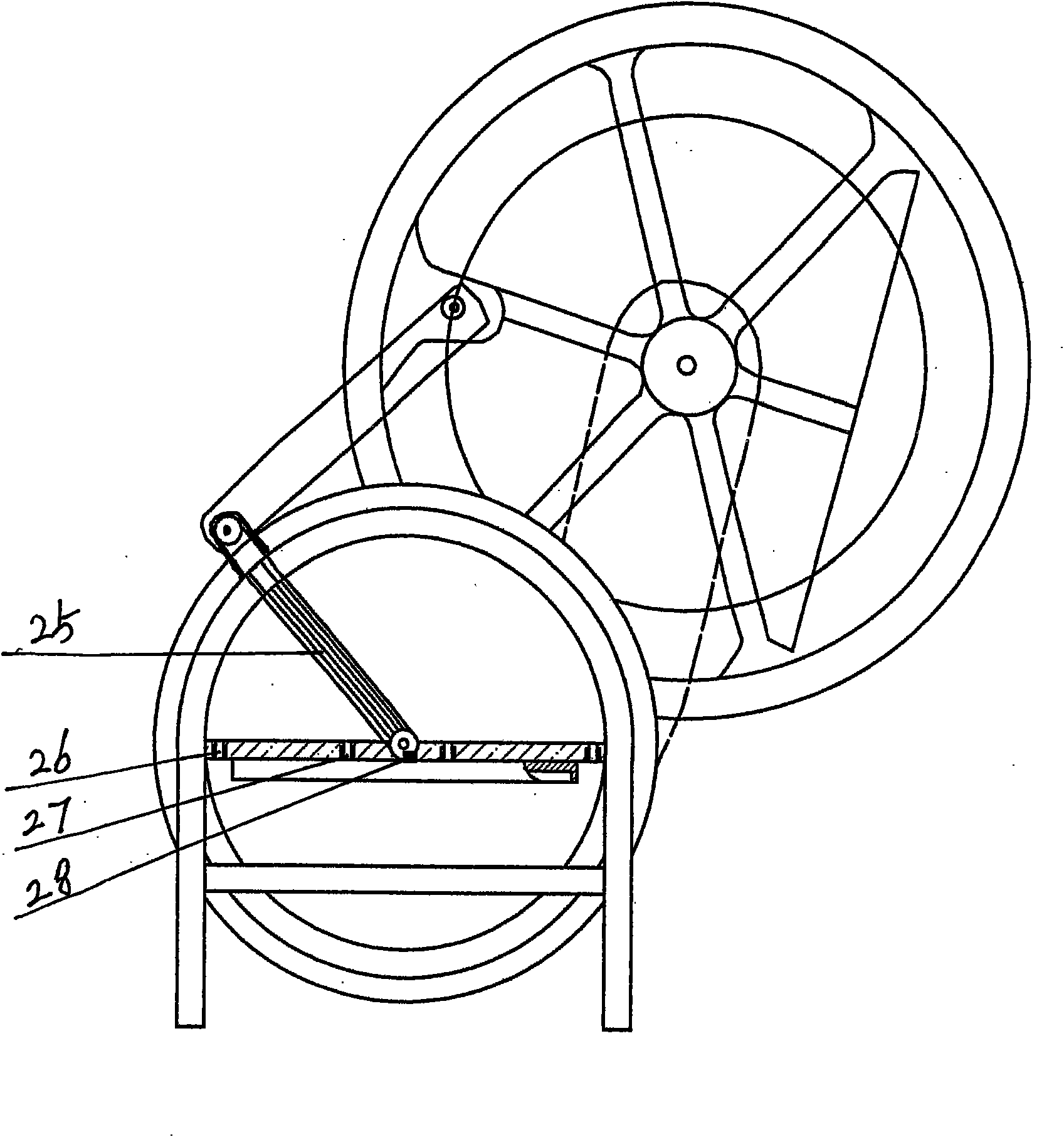
[0017] An energy-saving air compressor is composed of a frame (2), the difference is that the upper end of the frame (2) is connected to a rotating shaft (13), and there is a flat key (19) in the middle of the rotating shaft (13) to connect the Number machine (20), rotating shaft (13) connects bearing and tile seat (14) outer end connects right flywheel (18) and left flywheel (23) connects eccentric shaft (17) connects bearing (16) connects gland (21 ) Connect the connecting rod (15) The connecting rod (22) Connect the bearing (11) Connect the moving shaft (12) Connect the air pressure plate (25) The lower end of the air pressure plate connects the air pressure shaft (5) Connect the air pressure bearing and the seat (6) , connect the compressed air shaft gas ring (28) to connect the inch plate (4) the inch plate has air intake holes (26) exhaust holes (27) to connect the bottom water tank (3), and the upper end of the compressed air plate (25) is connected to the left and right mo


PUM


Abstract

The invention relates to an energy-saving air compressor comprising a stand (2). The energy-saving air compressor is characterized in that the upper end of the stand (2) is connected with a rotating shaft (13), and the middle of the rotating shaft (13) is provided with a flat key (19) connected with a substractor (20); the rotating shaft (13) is connected with a bearing and a bearing seat (14), and the outer end of the rotating shaft (13) is connected with a right flywheel (18) and a left flywheel (23); the right flywheel (18) is then respectively connected with an eccentric shaft (17); the eccentric shaft (17) is connected with a bearing (16); the bearing (16) is connected with a connecting rod (15); a gland (21) is connected with a connecting rod (22); a bearing (11) is connected with a movable shaft (12); the movable shaft (12) is connected with a pressure fan plate (25); the lower end of the pressure fan plate (25) is connected with a pressure fan shaft (5); the pressure fan shaft (5) is connected with a pressure fan bearing and a pressure fan bearing seat (6); the pressure fan bearing and the pressure fan bearing seat (6) are connected with a pressure fan shaft air ring (28); the pressure fan shaft air ring (28) is connected with an inch plate (4); the inch plate (4) is provided with an air inlet (26) and an air vent (27) and connected with a bottom water tank (3), and the upper end of the pressure fan plate (25) is connected with a left movable ring (1) and a right movable ring (1); a semi-circular head (8) is connected with an air ring (9); the outer end of the left movable ring (1) and the outer end of the right movable ring (1) are connected with a protector (10) and a water tank (7), and the lower end of the left movable ring (1) and the lower end of the right movable ring (1) are respectively connected with both sides of a stabilizer (24).

Description


Claims


Application Information

Patent Timeline
Owner 刘文
Why Eureka
Try Eureka