Load-bias free four row roller bearing for rolling mill

A cylindrical roller bearing and cylindrical roller technology, applied in the direction of roller bearings, bearing components, shafts and bearings, can solve the problems of bearing fatigue damage, short life of spherical roller bearings, and high maintenance costs, and achieve radial The effect of increasing the load bearing capacity, increasing the contact area of ​​the raceway, and improving the service life

Inactive Publication Date: 2009-11-25
瓦房店第一轧机轴承制造有限公司
View PDF0 Cites 0 Cited by
  • Summary
  • Abstract
  • Description
  • Claims
  • Application Information

AI Technical Summary

Benefits of technology

This technology improves the strength and durability of bearings used for vehicles by adding extra parts called side holding rings at either end of each part or increasing its number of columns within it. These technical improvements help reduce stress concentration that can lead to cracks during use over time while still maintain their effectiveness.

Problems solved by technology

The technical problem addressed by this patented technology relates to improving upon existing ball bearing designs that have been designed with specific loads or uses during their use without causing excessive wear on certain parts (such as balls) due to increased loading levels caused by heavy machinery being operated at different times throughout its lifespan).

Method used


Image

  • Load-bias free four row roller bearing for rolling mill
  • Load-bias free four row roller bearing for rolling mill
  • Load-bias free four row roller bearing for rolling mill

Examples


Embodiment Construction

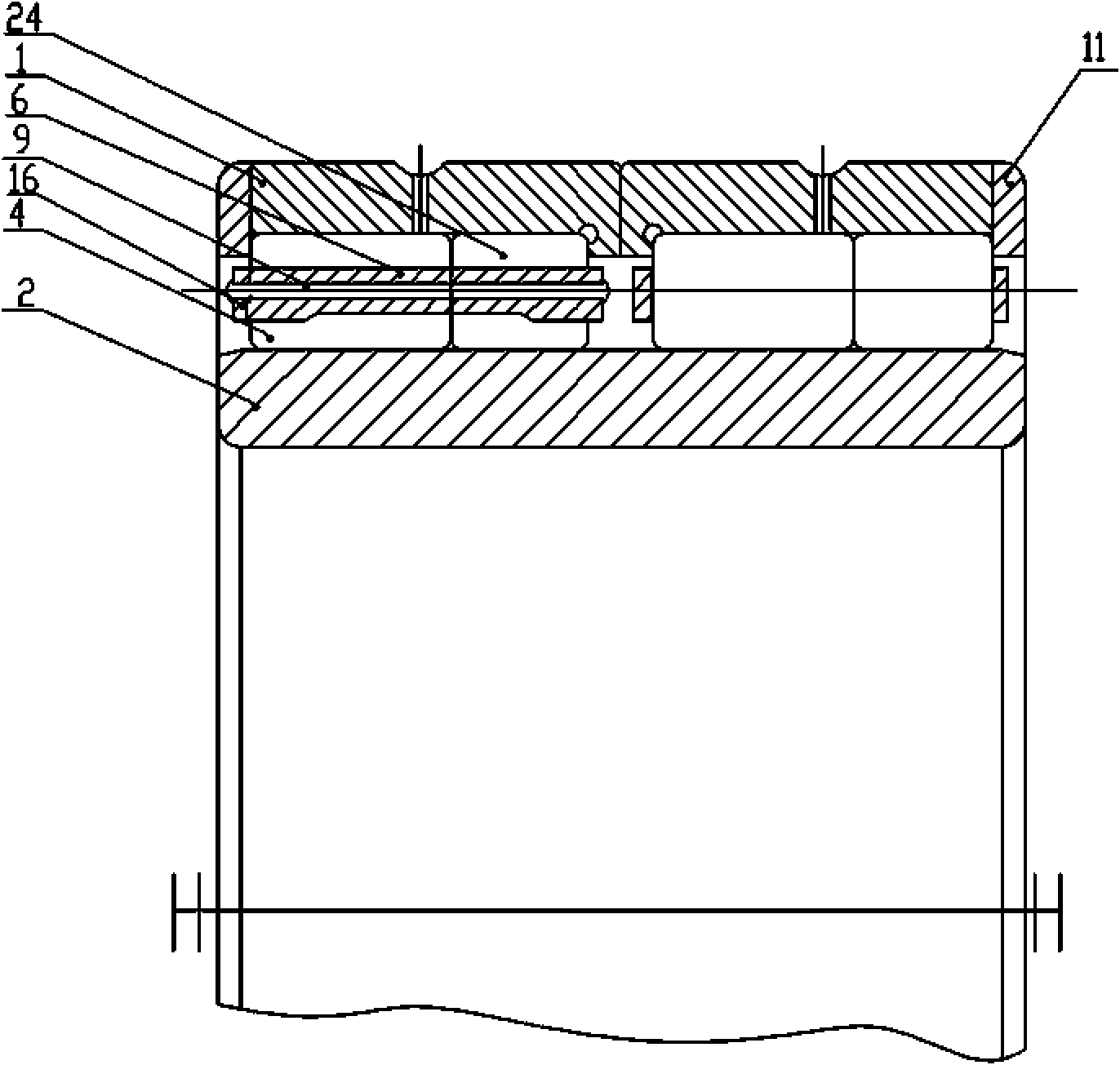
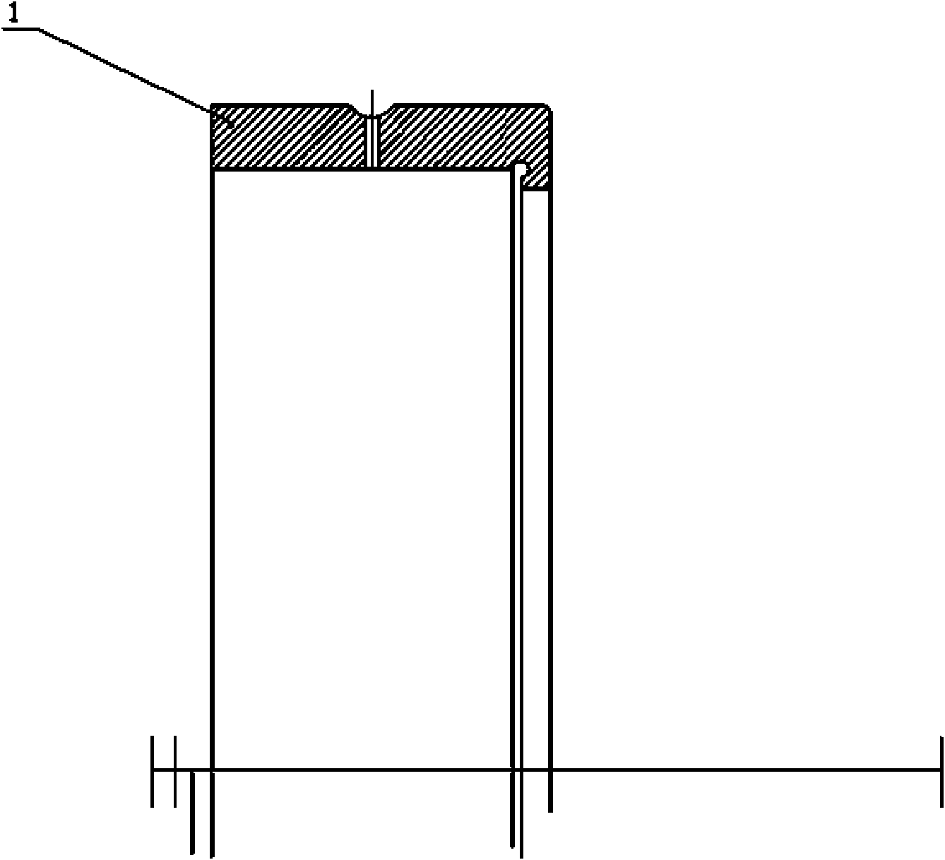
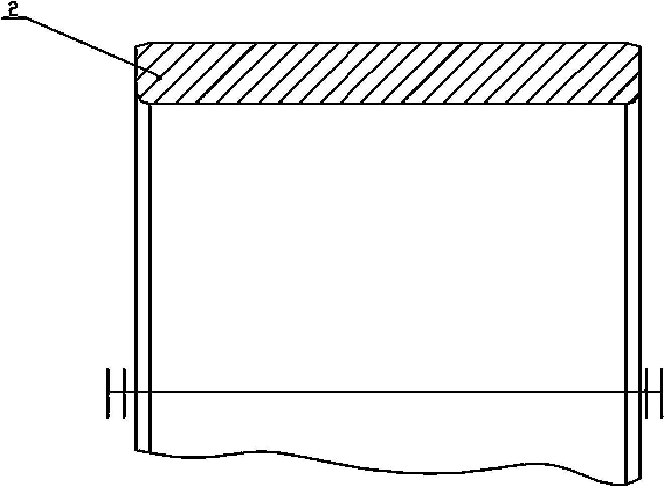
[0011] The specific implementation manner of the present invention will be further described below in conjunction with the accompanying drawings.

[0012] Such as Figure 1~4 As shown, a four-row cylindrical roller bearing for rolling mills with unbiased loads is provided with double outer rings 1 and inner rings 2 , and edge retaining rings 11 are provided on both ends of the outer ring 1 . There are two sets of cages 6 between the outer ring 1 and the inner ring 2, and the cage cover 16 is connected with the cage 6 through rivets 9. Two rows of cylindrical rollers are evenly distributed on each cage 6 along the circumferential direction. The length of one row of cylindrical rollers 4 in the first cage 6 is 1 / 4-1 / 2 longer than the length of the other row of cylindrical rollers 24.


PUM


Abstract

The invention discloses a load-bias free four row roller bearing for a rolling mill, which is provided with double outer rings (1) and an inner ring (2); and two groups of retainers (6) are arranged between the outer rings (1) and the inner ring (2), and each retainer (6) is evenly distributed with two rows of cylindrical rollers along the circumferential direction. The four row roller bearing is characterized in that two end faces of the outer rings (1) are provided with side retainer rings (11). The two end faces of the outer rings are provided with the side retainer rings, so that the radial load and axial load of the bearing are separately borne, and load-bias does not exist; and the length of two rows of cylindrical rollers is increased, so that the contact area of a raceway is increased, the radial load bearing capacity is increased correspondingly, and the service life is prolonged.

Description


Claims


Application Information

Patent Timeline
Owner 瓦房店第一轧机轴承制造有限公司
Why Eureka
Try Eureka