Inserting pin component of optical cable connector and tensile connecting structure of inserting pin component and optical cable

An optical fiber connector and pin technology, applied in the direction of fiber mechanical structure, etc., can solve the problems of difficult installation, lack of fixed and tensile structure, lack of sealing protection, etc., and achieve the effect of convenient installation

Inactive Publication Date: 2009-12-09
CHINA AVIATION OPTICAL-ELECTRICAL TECH CO LTD
View PDF0 Cites 11 Cited by
  • Summary
  • Abstract
  • Description
  • Claims
  • Application Information

AI Technical Summary

Benefits of technology

The present in this patented technology allows for securely attaching aramide fibers (AF) within cables while maintain their flexibility during deployment operations. This makes it easier than previous methods that had only fixed them at specific locations inside the jacket material.

Problems solved by technology

This patented technical problem addressed by this patents relates to improving an Optical Cable Connection (OCA) Connector's performance while maintaining its structural integrity during installation without compromising their ability to protect against external factors such as water or other contaminants from entering them through gaps formed when inserting and attaching wires inside the OCJ).

Method used


Image

  • Inserting pin component of optical cable connector and tensile connecting structure of inserting pin component and optical cable

Examples


Embodiment Construction

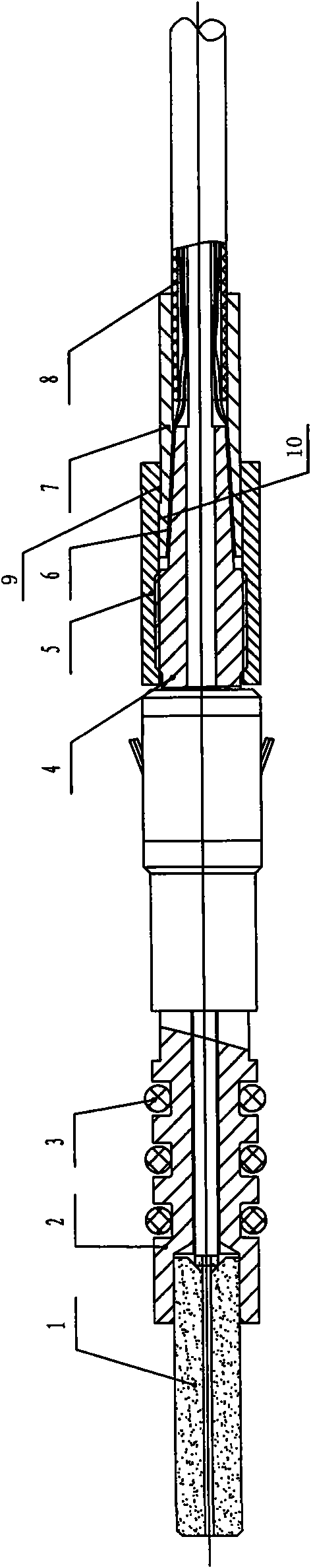
[0013] Such as figure 1 As shown, the pin part includes a pin 1, and the pin 1 is inserted in the front port of the flange 2, the rear end of the flange 2 is connected with the rear sleeve 4, and the outer ring of the flange 2 is along the shaft A plurality of annular grooves are arranged side by side, and O-ring seal rings 3 are fastened in each annular groove. The outer surface of the tail of the rear sleeve 4 has a tapered surface with a gradually smaller outer diameter. The taper sleeve 7 of closing structure, the nut 5 is movably assembled on the outer ring of the taper sleeve 7, the front end inner wall of the nut 5 is provided with an internal thread, and the front of the cone face of the back sleeve 4 is provided with an external thread column matching the internal thread of the nut 5 noodle. The joint surface between the inner ring of the nut 5 and the outer ring of the taper sleeve 7 is provided with an axial engagement structure. Along 10 poses. When in use, the ara


PUM


Abstract

The invention discloses an inserting pin component of an optical cable connector and a tensile connecting structure of the inserting pin component and the optical cable. A conical surface with gradually reduced external diameter is arranged on the outer surface of the tail part of a rear sleeve of an inserting pin component; a conical sleeve of which an inner ring is in a conical surface closed structure is correspondingly sleeved on the conical surface; a screw nut is movably assembled on an outer ring of the conical sleeve; an axial meshed structure is arranged on the combining surface between the inner ring of the screw nut and the outer ring of the conical sleeve; screwing match structures are arranged on the inner wall at the front end of the screw nut and the outer wall of the rear sleeve; an aramid fiber exposed from the cutting position of the outer skin of the optical cable is clamped between the outer surface of the conical surface of the tail part of the rear sleeve and the inner ring of the conical sleeve; the aramid fiber, the conical sleeve and the rear sleeve are fixed into a whole by the function of screwing locked force between the screw nut and the rear sleeve; when the optical cable is pulled by external force, the pulling force is exerted on the conical sleeve and the rear sleeve by the aramid fiber, and a center optical fiber can not be pulled; when a flange or the rear sleeve of the inserting pin component is pulled, the whole optical fiber can be pulled to move by the aramid fiber, thereby being free from the damage of the center optical fiber by pulling and leading the installation of the inserting pin component to be more convenient.

Description


Claims


Application Information

Patent Timeline
Owner CHINA AVIATION OPTICAL-ELECTRICAL TECH CO LTD
Why Eureka
Try Eureka